Continue to Site

Welcome to our site!

Electro Tech is an online community (with over 170,000 members) who enjoy talking about and building electronic circuits, projects and gadgets. To participate you need to register. Registration is free. Click here to register now.

  • Welcome to our site! Electro Tech is an online community (with over 170,000 members) who enjoy talking about and building electronic circuits, projects and gadgets. To participate you need to register. Registration is free. Click here to register now.

Ni-MH aaa battery charger

Status
Not open for further replies.

123mmm

Member
Hello! I would like to know if BD140 (Q1) can be replaced by BD244CG in the attached schematic ? I made a mistake on the PCB and I placed the TO-220 footprint instead of TO-126 (BD140) footprint.
I would also like to know if it is normal for the blue led to start fading out very slow when the batteries are fully charged ? Or the blue led should turn off instantly when the batteries are fully charged ?
 

Attachments

  • schematic.png
    schematic.png
    102.4 KB · Views: 237
Last edited:
As there's no hysteresis around the comparators the LED's will fade rather than switch - adding hysteresis to each comparator via high value resistors from outputs to +ve inputs, plus a resistor from final output back to the pin 5's, should make it switch rather than fade.

The BD244 should be fine, and is a much more powerful device.
 
Your simple circuit with many parts over-charges the battery cells which reduces their life.
A battery charger IC will detect the drop in voltage when a full charge occurs and shuts off.
Here is the voltage of a Ni-MH cell charging at various currents. The graph is from Energizer Battery Company:
 

Attachments

  • Ni-MH charging voltage.PNG
    Ni-MH charging voltage.PNG
    39 KB · Views: 189
There is nothing at all wrong with a charge circuit such as the OP shows, as long as the voltage limit is set correctly.

At that, the current should drop to a low trickle by the point the cells are fully charged, so no voltage drop detection is needed. The voltage curve would be somewhere between the blue and green lines in your image.
 
The blue and green charging curves in the image I posted merge and level out at a charging current of 0.15C.
But Energizer Battery Company and Battery unoversity.com say do not trickle charge at more than 0.025C.
 
do not trickle charge at more than 0.025C
Which it will not do - as long as the voltage is set properly!

That circuit has no continuous trickle facility, it will only cut it if the voltage is too low.
When charging, the current will taper to nothing as the cells come up to the set voltage.
 
The guy who made Eleccircuit.com admits that he is not an electronics expert and has poor English.
His "charger" circuit has many problems.

Battery University.com and Rechargeable battery manufacturers like energizer.com have Tech Info with details about how to charge their batteries. NiMH batteries are not fully charged when their voltage reaches a certain voltage. If the voltage is too high then the battery is destroyed.

1) The circuit does not say how many cells in series it charges.
2) The circuit uses a dual opamp instead of a single opamp. The unused opamp must be disabled.
3) The circuit uses a TL07x or TL08x opamp that have problems if an input voltage becomes closer than a few volts from ground.

Use a proper charger IC made for charging NiMH cells.
 
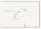
I would like to know if the circuit will still work correctly if I will replace the TL072 by TL082 and the MJE2955 by BD244C ?
It will probably work, but it is not an ideal charger. It will take anything from a two cells to possibly six cells, at a guess.
A single cell is unlikely to work properly due to the opamp not including the negative supply (0V in the circuit) in its common mode range; both the 07x and 08x only work down to 1.5V from the negative pin.

A rail to rail input one would be better, but it needs to be a FET or CMOS type ideally, something with very low input current.

The overall circuit appears to be a fixed high-current charge while on, and shut off when the cell voltage stops increasing, so it should work moderately well for high capacity cells. For AAA cells, increase the one ohm resistor to eg. five ohms so they are not damaged by too high a charge current.

It has no trickle charge capability, and an occasional long trickle charge (even after a normal full charge) is required to keep the cells in good condition, as is occasionally doing a full discharge to low voltage.

Trickle charging balances series cells in packs and also reforms the plate surfaces to prevent crystallisation.

You could add a resistor directly from the 12V input to battery positive, to give a low trickle; just around 2 - 4mA continuous will improve the battery state and they can be left at that for days, assuming they are 400mAH or higher.
 
I tested the circuit and I found that it is working, but I have a question: what is the normal behavior of the circuit when I plug the 12Vdc transformer into the 230Vac mains and then connect the 12V to the charger ? It is normal to start charging the batteries without pressing the button ?
 
What should I check ? I would like to find the problem that starts the charging process only when I press the button ?
 
What voltage are you supplying it with, and what voltage do you get across the output terminals, with no battery connected?

Also what voltages do you get on pins 1, 2 & 3 of the TL072 (with negative on the 0V / ground connection).
 
The supply voltage is 12Vdc. The voltage across the output terminals is 1.68V with no battery connected.
With no battery connected I have on pin 1 11.88V, on pin 2 1.66V and on pin 3 2.36V.
With 3x AA battery connected in series I got 1.64V on pin 1, 4.10V on pin 2 and 3.91V on pin 3.
 
OK, check D4 is the right way around and that C4 and C5 are properly grounded, and have connectivity to pins 2 & 3?

C4 has to charge faster than C5 when the battery is connected, to prevent the charge start being triggered.

Looking at the circuit again, the diode drop may well be enough to allow C5 to get ahead of C4 in that last few hundred millivolts, and trigger charge start.

The R2-D1 circuit should pre-charge C4, when power is initially switched on, but that will take several minutes to charge up before it's enough to prevent an automatic start..
 
Last edited:
I checked the mentioned connections and they are good. Also, I changed C4 with another 1000uF cap and D4 with 1N4007, but they didn't helped anything.
 
Last edited:
What happens if you leave it connected to power for half an hour or more before connecting the battery?
 
Status
Not open for further replies.

Latest threads

New Articles From Microcontroller Tips

Back
Top