Continue to Site

Welcome to our site!

Electro Tech is an online community (with over 170,000 members) who enjoy talking about and building electronic circuits, projects and gadgets. To participate you need to register. Registration is free. Click here to register now.

  • Welcome to our site! Electro Tech is an online community (with over 170,000 members) who enjoy talking about and building electronic circuits, projects and gadgets. To participate you need to register. Registration is free. Click here to register now.

newbie question , need help :(

Status
Not open for further replies.

newnew

New Member
hello
i was playing with an optical switch
the circuit works , i just used a 4k resistor instead of the 100k one
but i dont understand how it works !!

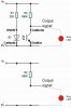
in the photo transistor part, the signal out before the transistor . so if for example i connected a led , one lead will be connected to the resistor and the other to ground, it will be as if i just connected the led normally to a supply voltage ,
shouldnt it supposed to be connected one lead to resistor and the other to collector of the photo transistor .

also can i connect the output directly to a pic ?

thanks
 

Attachments

  • opto002.gif
    opto002.gif
    2.5 KB · Views: 172
Look up the data sheet for your photo-interrupter. There is a very important spec called "Current transfer Ratio" The typical CTR for these is like 0.5, meaning if you drive the source LED with say 10mA, you get like 5mA at the collector of the photo-transistor. This gives the info required to pick the load resistor...
 
this is a generic type photoswitch , i can only see 860D written on it, and i cant find anything about it
however thats not my question,
i was thinking if i removed the photo switch from the circuit , it will be just a led connected to +5V and ground through 4k resistor, thats all.
 
first of all, the 100k acts as a pull up resistor, so that was why u were able to change it. the higher the resistance, the more sensitve the circuit becomes.

Your sensor sends gnd to the output when it receives enough light, which means if an led is connected between the output and gnd it will not turn on

But if the light received by the sensor is low, the resistance of the sensor becomes high and the led turns on. it is safer you use the ouput to switch the led.
this circuit can also be applied in street lights controle, with few components added
 
i was thinking if i removed the photo switch from the circuit , it will be just a led connected to +5V and ground through 4k resistor, thats all.

the LED is IR not visible light if that is what you are asking...
 
hmm, i am not sure i understand that
any math to clear things up ??
i just replaced 100k with 4k so the circuit can work
offcourse i know its IR led
any way thats what i mean
look at these attached files, if i remove the switch it will be just like i connect a red led to supply through resistance , so what is the function of the switch ?
draw enough current so the led can turn on ?
why isnt the led draw its needed current ? cause of the resistance limiting the current, so if it limit the current it will limit it to the transistor as well ?
i still dont get it.
 

Attachments

  • Graphic1.jpg
    Graphic1.jpg
    18.2 KB · Views: 122
Your circuit has a 100k resistor limiting the current to the red LED so the current will be very low and the LED will be very dim.
When the photo-transistor turns on it will short the red LED and the LED will turn off.

If the current-transfer ratio of your optical isolator is high then the value of the 100k resistor could be much lower for better red LED brightness.

The red LED can be connected in series with the photo-transistor and current-limiting resistor then it will light when the photo-emitter is active.
 
Status
Not open for further replies.

Latest threads

New Articles From Microcontroller Tips

Back
Top