Continue to Site

Welcome to our site!

Electro Tech is an online community (with over 170,000 members) who enjoy talking about and building electronic circuits, projects and gadgets. To participate you need to register. Registration is free. Click here to register now.

  • Welcome to our site! Electro Tech is an online community (with over 170,000 members) who enjoy talking about and building electronic circuits, projects and gadgets. To participate you need to register. Registration is free. Click here to register now.

New Member - Knight Rider Voice Box

Status
Not open for further replies.
audioguru

audioguru

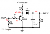
that new schematic...

on the far left where it has input

the bottom wire that goes out into the left into the abyss....

am i to assume its positive input on the top of the phonejack/audio input.

and on the bottom of the 1/8 phonejack and negative lead that goes nowhere on the schematic?


or whats the interpretation?
 
Each channel of the MP3 player has a live signal wire and an output ground wire.

The input to the VU meter circuit is the live signal and the input ground (at the lower left on the schematic) is from the ground wire of the MP3 player. Use shielded audio cables.
 
i built the circuit with the pre-amp.

all the leds light up.

no audio input.

they just light up when power is connected.

where can the short be?
 
Did you build it exactly like Uncle $crooge drew it? ie: Did you include R4, the 100K POT, in the circuit?
 
Did you build it exactly like Uncle $crooge drew it? ie: Did you include R4, the 100K POT, in the circuit?

yes i did, ive been following the wiring and it all looks correct. im sure its something stupid just not sure where to look now

as soon as i apply power, al the leds light up and stay there. audio input or not doesnt affect it.
 
Without an input signal:
1) Measure the voltage at the base of the transistor. It should be 0V.
2) Measure the voltage at the emitter of the transistor. It should be about +0.65V.
3) Measure the voltage at the cathode of the diode. It should be 0V.

When the input of the LM3915 is 0V then no LED should be lighted.
 

Attachments

  • peak detector again.PNG
    peak detector again.PNG
    10.5 KB · Views: 531
Status
Not open for further replies.

Latest threads

New Articles From Microcontroller Tips

Back
Top