Continue to Site

Welcome to our site!

Electro Tech is an online community (with over 170,000 members) who enjoy talking about and building electronic circuits, projects and gadgets. To participate you need to register. Registration is free. Click here to register now.

  • Welcome to our site! Electro Tech is an online community (with over 170,000 members) who enjoy talking about and building electronic circuits, projects and gadgets. To participate you need to register. Registration is free. Click here to register now.

New Member - Knight Rider Voice Box

Status
Not open for further replies.

Kentley

New Member
Firstly, i would like to introduce myself. I have recently (6 weeks) started a national diploma at college in electronics. So far, I have suprisingly found it really interesting and therefore have started to take interest in formus like this one.

I have just finished making a bargraph display on breadboard, a knight rider scanner with a 1458 and a lm3914 chip, and have been looking on the net for other ideas.

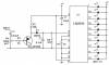
I came across the schematic diagram of "shunters", which uses a lm3915 ( same as the lm3914 - correct me if im wrong)...

https://www.electro-tech-online.com/attachments/voiceboxmodified-jpg.12975/

As, on a youtube series of videos created by shunter, Part 1 (https://uk.youtube.com/watch?v=V4s7JiWgoaM&feature=related) of the series shows him putting a mp3 player into the system, and playing the knight rider theme tune through a amplifier and speaker. The voice box also reactes to this. i understand everything.

Now, the bits i dont understand...

How to wire up the 6 displays (cathodes and anodes)
Do you need the transistors as it states that you may not need these
And...probably the main bit... the audio transformer. I assume that this is where i woulod plug my mp3 player into the curcuit.

I would appreciate it if someone could explain as much as they can about this curcuit. Mainly, the audio bit i.e. amplifier, speaker and mp3 input.

Sorry if my terminology is wrong.

Thanks
 
Last edited:
With just two bar graphs, a left and a right as shown in the YouTube video, you don't need the transistors. To drive more displays, you'll need the transistors if the LEDs are to be bright enough.
Where is says "Audio In" in the upper left hand side of the diagram is where you connect the MP3 player. There is a mistake on the diagram as far as the transistors are concerned. The emitters should be connected to +12V and the "regulator" eliminated as you already have a 12V supply. There should also be a envelope detector feeding the IC so that the LEDs "dance" to the music better.
 
Last edited:
Thanks for the reply but i still need some answers...

1) I am using 3 bargraphs as the KITT would have so do i need the transistors
2) I still dont know which sides are the anodes and cathodes on the bargraphs on the diagram.
2)I am ordering my stuff from maplins and need to know what things i need to buy

It says on the diagram:
- a 1uF Capacitor, will a low profile SE Series Radial Electrolytic work and what voltage do i need (**broken link removed**)

- 10k Variable Resistor,will a square 22 turn cermet preset 10k petentiomer work? (**broken link removed**)

- 1k 1/4 Watt Resistors - Maplins dont seem to do 1/4 watt so will 0.6 watt be ok? it suggests on their site that they will.(https://www.maplin.co.uk/Module.aspx?ModuleNo=2162

- again, will the 0.6 watt resistor be ok to replace the 1/2 watt 180 ohm.

- Now for the Audio in bit, Shunter shows a mono amplifier, I need to know which kit to buy from Maplins. I need to know out of the list (**broken link removed**) which one to buy.

And finally, the voltage regulator, do i need a fixed one and do i need a low dropout or positive one e.t.c

I would really appreciate if any of you could answer these questions as I really want to build this curcuit.

Thanks
 
2) I still dont know which sides are the anodes and cathodes on the bargraphs on the diagram.
Without the transistors driving 2 bargraphs: The anodes of one bargraph go to the positive supply rail. (The same as pins 3&9 of the LM3915) Then the cathodes go to the anodes of the 2nd bar graph (The mirrored one). The cathodes of the 2nd bar graph go to the LM3915s outputs.
With transistors, driving a multiple of 2 bargraphs ( 4,6,8,etc): The anodes of one bargraph go to the collectors of the transistors. Then the cathodes go to the anodes of the 2nd bar graph (The mirrored one). The cathodes of the 2nd bar graph go to ground via the resistors. The emitters of the transistors go to the supply voltage. Parallel enough of these up to make a thicker bar. Making it a thicker and longer bar requires a little more complexity which is best expressed with a schematic.
It says on the diagram:
- a 1uF Capacitor, will a low profile SE Series Radial Electrolytic work and what voltage do i need (**broken link removed**)
Anything over 16V will work fine.
- 10k Variable Resistor,will a square 22 turn cermet preset 10k petentiomer work? (**broken link removed**)
Overkill, but it'll work. A single turn pot is OK also.
- 1k 1/4 Watt Resistors - Maplins dont seem to do 1/4 watt so will 0.6 watt be ok? it suggests on their site that they will.(https://www.maplin.co.uk/Module.aspx?ModuleNo=2162
- again, will the 0.6 watt resistor be ok to replace the 1/2 watt 180 ohm.
That's OK. It is always OK to get a HIGHER wattage resistor of the same type. Don't sub a wirewound resistor for a carbon one unless you know what you're doing.
- Now for the Audio in bit, Shunter shows a mono amplifier, I need to know which kit to buy from Maplins. I need to know out of the list (**broken link removed**) which one to buy.
It depends on how loud you want it. You don't need the amp for the display. Your MP3 player will probably output enough level for that.
And finally, the voltage regulator, do i need a fixed one and do i need a low dropout or positive one e.t.c
I would leave it out entirely. What do you have for a power source?
 
Last edited:
Thanks again kchristie.

I intend to power 6 bargraphs - 3 bargraphs...mirrored as kitt would be (https://www.electro-tech-online.com/attachments/voiceani-gif.406/). So will i need the transistors and how will i wire the andodes and cathodes.

I thought that i would need the amp to feed the curcuit and a speaker. If you say that i do not need to use one how do i wire the mp3 player up into the curcuit.

I can use a 12v or 9v supply. Whatever is needed/better. So will i need the regulator and which ones.

Cheers.
 
Oh and I heard somewhere that the voltage regulator was to create the fading action on the bargraphs. Whether this infuences me needing it i dont know.
 
As per your PM,
Oh and I heard somewhere that the voltage regulator was to create the fading action on the bargraphs.
It shouldn't be needed/used for that. The voltage regulator's function is to supply a steady voltage source for the circuit. It would only be helpful if you are concerned that the LEDs will change brightness slightly with supply voltage. ie: The battery voltage in your car will vary between 12.5V when parked and 15V when running.
If you want to plug it into the wall, get a power supply that is regulated. If you buy something like **broken link removed** then you won't need the regulator at all. You need one with at least 1200ma output because 60 LEDs @ 20ma = 1200ma.
If you say that i do not need to use one how do i wire the mp3 player up into the curcuit.
Wire the "audio in" on the diagram to a plug the same as your MP3 headphones. You can leave the center ring of the plug unconnected and the KITT will take audio from the left or right channel only which should be good enough. You could sum the left and right channels with some 100Ω resistors but I think it is unnecessary.
 
Hello kchriste

I was looking for K.I.T.T. schemes and i found this thread where u are speaking about shunter's scheme. This thread was very useful but im not sure understand you (my bad english/ my bad electronics knowledges). Is this scheme right with all u say? My corrections are the blue color.

**broken link removed**

Thanks.
 
Yes, you have wired the LEDs correctly with the "blue" wires. If you find that the LEDs dance too quickly, you'll need to add an envelope detector on the input of the LM3915. Try it first and see.
 
Thanks very much. I dont know what is a envelope detector; a component? a little circuit? Im looking for spanish for that.
By the way... I have seen u say about audio amplifier;

"It depends on how loud you want it. You don't need the amp for the display. Your MP3 player will probably output enough level for that."

Do u means the audio transformer in the scheme?
And finally Dont i need what transistors i need? The only info i seen is it are PNP but i think i need any more? Right?
 
Thanks very much. I dont know what is a envelope detector; a component? a little circuit? Im looking for spanish for that.
It is also called a peak detector. Here is one from the datasheet:
https://www.electro-tech-online.com/attachments/peak_detector-gif.3660/
By the way... I have seen u say about audio amplifier;
"It depends on how loud you want it. You don't need the amp for the display. Your MP3 player will probably output enough level for that."
Do u means the audio transformer in the scheme?
No. I think Kently was talking about an audio amplifier for his MP3 player so he could hear it via speakers.
And finally Dont i need what transistors i need? The only info i seen is it are PNP but i think i need any more? Right?
That depends on how many LEDs you are going to use. PN2907A will work for up to apx 200 LEDs ( 20 bargraphs of 10 LEDs each) assuming a LED current of 20ma and two LEDs in series per string.
If you just want to have 20 LEDs made up of 2 bargraphs, then you don't need any PNP transistors at all.
 
design project

dear, i am graduating in electrical engineering & looking for some graduating electronics design specially on control,or communication.can help me?
 
Last edited:
so what is the audio transformer for? part number and value? and where can u get it?

and can we post a final schematic we call can agree works? please theres been so many tweaks i cant keep up?

i'm going to get the 160-1066-nd br graphs with the lm3915 ic chip

so all i cant figure out is the audio transformer so can someone please shed some light on this?

and the updated schematic with corrections in blue for the transistor connection is that the way to go?.

i don't need a output, the bar graph is the out put . im inputting from a car computer using 1/8 headphone jack cable.


so any help guys?
 
The LEDs will look like a dim blur without the peak detector circuit shown in the datasheet of the LM3915.
The transformer is an old fashioned joke. An electronic preamp circuit with a volume control should replace it.
 
thanks

thank you, would anyone be kind enough to help me out here.i took electronics in high school and got a trade degree in it. but im just a little rusty.

where can i get
"An electronic preamp circuit with a volume control

and why do i need a volume control?

jsut want the led bars to move with the audio input. just as a visual display.

i'll have a y-cord coming from my car computer sending the input to my car stereo aux jack for sound to my speakers and then also send to my kitt voice box to just display


so can someone update the schematic to adapt a more realistic better way to perform? with part numbers and values?


thanks guys. i hope im not asking too much.


let me know what i can do to help with this process
 
another dumb question sorry

when you guys said put a peak detector on the input of the lm3915 ic

did you mean the 12v input to pins 3/9

or after or before the 1uf capacitor? or before or after the 10k poteniometer?

sorry guys just trying to be very clear on what you guys are saying.


so after the audio input jack replace the transformer with An electronic preamp circuit with a volume control

then add a peak detector. then continue with the rest of the schematic?

and just get rid of the voltage regulator and reconnect the transistors according to the new schedmatic in blue corrections?
 
A preamp is needed if you use a microphone as an input.
Here is a circuit of a VU meter with a simple detector circuit. The input can be from your MP3 player.
 

Attachments

  • VU meter.PNG
    VU meter.PNG
    11.6 KB · Views: 8,008
Status
Not open for further replies.

Latest threads

New Articles From Microcontroller Tips

Back
Top