Continue to Site

Welcome to our site!

Electro Tech is an online community (with over 170,000 members) who enjoy talking about and building electronic circuits, projects and gadgets. To participate you need to register. Registration is free. Click here to register now.

  • Welcome to our site! Electro Tech is an online community (with over 170,000 members) who enjoy talking about and building electronic circuits, projects and gadgets. To participate you need to register. Registration is free. Click here to register now.

report water level in flower box

Status
Not open for further replies.
I am trying to make an easy way to alert me when i need to water a plant - a red led light. For now i am trying to do it without external power or solar panels - batteries only. I have everything figured out except the element that will detect when contact between 2 points in soil no longer conduct electricity and switch on the led light powered by battery.

I could do that using a relay, but relay consumes a lot of energy, it would drain a battery very soon. I would like to keep the energy usage zero or minimal unless the led light needs to shine. In a way i would need 2 elements:

1) something like relay, but made for small currents that uses very little electricity
2) a negation element of sorts - because lets say i have a relay, when current can flow between 2 points in soil (water level OK), it can therefor be used to switch on the relay and the led light will turn on. But that is not what i need - i need the exact opposite, i need the relay to turn on when current cannot flow between 2 points.

The solution is probably very obvious to most with knowledge, i hope you can direct me in the right direction.
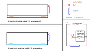
idea.png
 
But that is not what i need - i need the exact opposite, i need the relay to turn on when current cannot flow between 2 points.

A small N-MOSFET, like BS170, could be used. A 1Meg resistor connected between Bat+ (4.5V or 6V) and the gate can turn on an LED (with a limiting resistor in series). Sensing the soil resistance is between the gate and the source (connected to Bat-). This is what I try to test first if I need to take care of a flower box :)
 
Permanent meter electrodes tend to dry out fast at the surface and oxidize (insulate) the electrode surface when DC current is measured. A far more reliable method detects the % of H2O by the capacitance of water being 80 times air.
 
Permanent meter electrodes tend to dry out fast at the surface and oxidize (insulate) the electrode surface when DC current is measured. A far more reliable method detects the % of H2O by the capacitance of water being 80 times air.
Yes, you are right. To sense the water resistance or capacitance, an AC (not DC) current prevents the polarization of the sensor's electrodes which increases the sensed resistance continuously.

In this particular situation, I guess a very simple circuit with about 6uA DC current could be a good practical solution. Once a while, one can clean the thin isolating layer on the electrodes (usually they are made of chrome metal to avoid their oxidation by water). After all, we are talking here about a nice flower box :)
 
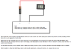
Before i ask about a mosfet, i had another idea ... instead of a LED light i could just use that cheap thermometer/humidity meter i have. This small meter can last a year on a single LR44 battery, which means it will last a long time if i use AAA battery. I only need the battery to last 6 months, after that i clean all parts and recharge for next year. Could this idea work ? Resistance of this screen thermometer is 4.300.000 ohms.
 

Attachments

  • simple idea.png
    simple idea.png
    71.5 KB · Views: 183
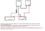
Ok, since no one responded to that simple idea i will ask about mosfets now. Kerim, you mentioned the mosfet for this job. I did some searching and i understand kind of how mosfets work now. If chatgpt is correct, the switching action of the mosfet is insanely low cost as far as energy consumption goes, it can do many switches on a single battery (though i doubt that is correctly calculated ... chatgpt said if a mosfet would switch every 3 minutes, it would take it 273 years to use 2000mAh of juice. That seems excesive). Ok, so here is the text and scheme. Now i need to pick the correct mosfet and understand how long a 2000mAh battery will last.
 

Attachments

  • scheme.jpg
    scheme.jpg
    157.6 KB · Views: 188
I am trying to make an easy way to alert me when i need to water a plant - a red led light. For now i am trying to do it without external power or solar panels - batteries only. I have everything figured out except the element that will detect when contact between 2 points in soil no longer conduct electricity and switch on the led light powered by battery.

I could do that using a relay, but relay consumes a lot of energy, it would drain a battery very soon. I would like to keep the energy usage zero or minimal unless the led light needs to shine. In a way i would need 2 elements:

1) something like relay, but made for small currents that uses very little electricity
2) a negation element of sorts - because lets say i have a relay, when current can flow between 2 points in soil (water level OK), it can therefor be used to switch on the relay and the led light will turn on. But that is not what i need - i need the exact opposite, i need the relay to turn on when current cannot flow between 2 points.

The solution is probably very obvious to most with knowledge reggie hayes net worth, i hope you can direct me in the right direction.

View attachment 140893
One possible solution for your project could be using a moisture sensor. Moisture sensors are designed to detect the moisture level in the soil and can be used to trigger an action, such as turning on an LED light, when the moisture level drops below a certain threshold.

There are different types of moisture sensors available in the market, but one common type is a resistive moisture sensor. Resistive moisture sensors work by measuring the resistance between two electrodes that are placed in the soil. When the soil is moist, it conducts electricity, and the resistance between the electrodes is low. However, when the soil is dry, the resistance increases, and the sensor can detect this change.

To use a resistive moisture sensor to trigger an LED light, you can connect the sensor to a microcontroller or a timer circuit. The microcontroller or timer can be programmed to turn on the LED light when the resistance of the moisture sensor reaches a certain threshold. This way, the LED light will only turn on when the soil is dry, and you can conserve battery power.

You can find many tutorials and guides online on how to use resistive moisture sensors with microcontrollers or timer circuits. Make sure to select a moisture sensor that is suitable for your application and has a low power consumption to maximize battery life.
 
In my experience DC Resistive moisture electrodes quickly corrode , very low current AC are better , but over time the same. Perhaps something that changes colour , or shrinks / expands with moisture could work .
 
The resistance values have a much wide error due to surface dryness and fertilizer and mineral salts act has conductors but are not levels of moisture content. So it is very unreliable for most soils. This doesn't even account for electrode oxidation may be a lesser problem.
 
all you need is low voltage CMOS 3V relaxation osc. and measure soil capacitance with a reference C and diode detector and comparator. To save power use low duty cycle uC in sleep mode.
 
I am still looking for the name of the mosfet that will do what i want it to do. Meaning, it is normaly closed and will open when it detects high state. For detail see my previous post with scheme.
 
You are looking for something that is not a reliable method. The resistance method is poor and this way does not compare resistance to a reference with Vgs which has a 2:1 range at 100uA. I suggest you do more research.
 
Last edited:
You need a DMM then learn more by putting in two metallic electrodes in soil after watering and measure resistance, every day without moving them or use an extra pair that you make random measurements and compare.

A FET will fail randomly too wet or too dry , since it is not calibrated and for reasons already stated. So this is a time waster.
 
I am still looking for the name of the mosfet that will do what i want it to do. Meaning, it is normaly closed and will open when it detects high state. For detail see my previous post with scheme.

MOSFETs do not work like that.

To do what you want, connect the source of a FET to power (battery) negative, the drain to the negative of the indicator or sounder, and the positive of the indicator/sounder to battery positive.

Add a high value resistor between gate and battery positive, so the FET turns on with no other connection.

Connect the electrodes in the plant to the FET source and gate. The electrodes should be stainless steel wire, to minimise corrosion.

The MOSFET must be a type that will turn fully on with a gate voltage less than the battery voltag.


If the moisture (and conductivity) is enough to keep the gate below the threshold voltage, the FET will stay off.

As the moisture level drops, the gate will go more positive and the FET start to turn on.

Try a one megaohm resistor between gate and power to start with & see if that is OK, too sensitive or not sensitive enough.


To reduce power consumption and electrolytic effects, you could add a CMOS oscillator to generate short pulses every few seconds, and feed the gate resistor from that instead of positive power.

That would also then give a flashing or pulsing alarm signal rather than a continuous one.


You could use the gates of a CD4093 CMOS IC for both the oscillator and a switch in place of the MOSFET.
Thank you, yesterday i ordered a bunch of different MOSFETS and i just ordered this CD4093. Its mostly about me learning things about electronics, i will get back to you when i actualy get the chips if i needed some help. Since u are here and always on point, 2 quick questions:

1) I made the little tester as shown in this post. So far its working, your thoughts ? POST
2) Just for fun i also ordered this gadget. LINK
 
What my DMM resistance test will tell you is that you will get more variation by moving the probes than by soil evaporation. Since the metal does not absorb moisture, the metal surface becomes a DC insulator before the soil does. Whereas measure AC resistance with an Oscillator source and measure AC voltage drop

If you just want to use a probe like your finger to measure moisture resistance, that will give you a fresh reading ok. But the surface may dry quickly and rise more than the soil. and then may corrode faster than you expect. Most people want a 24x7 monitor that is inexpensive. Inserting your finger in the soil is how gardeners might do it.
 
1) I made the little tester as shown in this post. So far its working, your thoughts ? POST
2) Just for fun i also ordered this gadget. LINK
I can't make out that first one..

The aliexpress gadget uses two different metals to form a voltage generating cell, like the old demo of sticking two different metal strips in an orange or lemon etc.

The cell operates the meter directly and the cell efficiency depends on how wet the soil is.

The electrodes are slowly breaking down - and polluting the soil with metal salts - all the time it's in the soil. OK for a brief test but not for leaving set in anything.
1. its really simple. I stick 2 electrodes into soil. And i connect them both to that temperature meter. Current only flows from 1 electrode to 2 electrode when soil is conducting electricity. When it does, a small battery is powering up the temperature meter. So far it seems to work. I am using copper electrodes and testing how long it will work. I need it to work for 6 months, after that i remove it and clean the whole thing. I am only using temperature meter as a screen or indicator - not to actualy measure the temperature, i am using it because it can run a very long time on a battery, months or years on AA battery.

Screen being turned on should mean that soil is somehow wet. I would prefer a red led light turned on when soil is dry but this is still better than nothing.
I also made a little thing with red led light but that is only made to stick into soil, measure and then put out of soil. Its working wonderfuly but its manual labor. I am waiting for all the chips to arive so i can do a better version that you suggested. Also i will make a version with an esp8266 for me at home but here i can use socket electricity and dont have to worry about mattery running down. Then i can simply measure every 20 minutes and light a led light (or send sms) when a certain soil needs watering. But when i have to rely on battery i cant do such operations unless i want to replace battery every week or use solar panels
 
Status
Not open for further replies.

Latest threads

New Articles From Microcontroller Tips

Back
Top