Hello all, this is my first post here. I've been into electronics for a couple years, but I'm just a hobbyist and always trying to learn.
I've attached a schematic I've drawn up for what I'm trying to do. I apologize for how messy it is, I'm not familiar with any formal rules for generating schematics. Any pointers there would be fantastic.
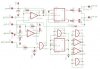
Anyway, it's an ignition splittler to convert a single ignition line output from the engine ECU into dual signals to run a wasted spark setup using a pair of coilpacks.
Inputs are:
Power- 12V automotive
IGT-ECU- this is the ECU's trigger line. it is pulled to +12V via a 1k resistor. the ECU pulls this line to ground to begin charging the coil, and releases ground to interrupt the current to fire the coil and produce spark. this is used as the clock signal to the 4013, as well as the ground reference to the output transistors. the 1N4004 is there to prevent the 12V on the source of the output Q from damaging the transistor when G is low. i'm not sure if this is necessary or not?
CYP- this is the cylinder position sensor. it is a VR sensor in the distributor that produces a negative voltage first, then crosses zero and goes positive. this is fed to the 339 to produce a 0-VDD pulse whenever the engine is between cylinders 3 and 4, in order to sync the circuit to the firing order of the engine.
STA- this is a 12V signal present only when the engine is cranking. this signal is clamped via a 12V zener since it's connected to a relay in the engine harness, and AND gated to the CYP pulse so that the reset pin is only pulsed high and the circuit is only synced while the engine is cranking. after it's sync'd, the output should be correct, and i didn't want to take the chance of the sync pulse coming and changing the state of the 4013 while one of the coils was in its dwell period.
-Ground
Outputs are:
IGT 1/4 and IGT 2/3 Both of these outputs are open collector that's connected to the igniter that drives the coil. Each igniter is internally pulled to 12V via a 1k pullup, so they must each be able to pull that line to ground to charge the coil. On the stock system, it is this pullup that pulls the ECU IGT line to 12v and the ECU pulls it low to charge the coil. If the ECU does not see 12V on this line, it throws a CEL for a bad igniter. That's the reason for the other internal pullup I mentioned on the IGT ECU input...
The idea is to transfer the IGT pulse to only one igniter at a time by using the 4013 to only allow one of the transistors to conduct at a time, then switching to the other after the coil has fired.
The issue is I can't seem to get it to toggle as it should. I'm using the output transistors to drive LED's at the moment instead of the igniters, but it still doesn't toggle reliably. I've tried debouncing the switch I'm using to emulate the IGT line, and the comparator on the IGT line is there to ensure that the clock edges are fast and clean. It "somewhat" works on the bench, but doesn't work at all when connected to the car (I'm just tapping the outputs, not actually wiring it in with the coils yet).
I don't know if the problem is that the switch is still bouncing, if i'm violating the clock edge maximums, if I'm violating the data setup time minimums or what.. All I can tell is that despite a clock pulse, the outputs do not change, even with D connected to /Q. I've done some searching both here and on the net in general and haven't seen anything that seemed to answer my questions.
I can't afford a real scope either, but I'm waiting on parts to build an ADC to LPT port converter for the "Scope on PC" to use for now..
Any pointers, ideas, and/or criticisms are welcome. Thanks!
-karl
I've attached a schematic I've drawn up for what I'm trying to do. I apologize for how messy it is, I'm not familiar with any formal rules for generating schematics. Any pointers there would be fantastic.
Anyway, it's an ignition splittler to convert a single ignition line output from the engine ECU into dual signals to run a wasted spark setup using a pair of coilpacks.
Inputs are:
Power- 12V automotive
IGT-ECU- this is the ECU's trigger line. it is pulled to +12V via a 1k resistor. the ECU pulls this line to ground to begin charging the coil, and releases ground to interrupt the current to fire the coil and produce spark. this is used as the clock signal to the 4013, as well as the ground reference to the output transistors. the 1N4004 is there to prevent the 12V on the source of the output Q from damaging the transistor when G is low. i'm not sure if this is necessary or not?
CYP- this is the cylinder position sensor. it is a VR sensor in the distributor that produces a negative voltage first, then crosses zero and goes positive. this is fed to the 339 to produce a 0-VDD pulse whenever the engine is between cylinders 3 and 4, in order to sync the circuit to the firing order of the engine.
STA- this is a 12V signal present only when the engine is cranking. this signal is clamped via a 12V zener since it's connected to a relay in the engine harness, and AND gated to the CYP pulse so that the reset pin is only pulsed high and the circuit is only synced while the engine is cranking. after it's sync'd, the output should be correct, and i didn't want to take the chance of the sync pulse coming and changing the state of the 4013 while one of the coils was in its dwell period.
-Ground
Outputs are:
IGT 1/4 and IGT 2/3 Both of these outputs are open collector that's connected to the igniter that drives the coil. Each igniter is internally pulled to 12V via a 1k pullup, so they must each be able to pull that line to ground to charge the coil. On the stock system, it is this pullup that pulls the ECU IGT line to 12v and the ECU pulls it low to charge the coil. If the ECU does not see 12V on this line, it throws a CEL for a bad igniter. That's the reason for the other internal pullup I mentioned on the IGT ECU input...
The idea is to transfer the IGT pulse to only one igniter at a time by using the 4013 to only allow one of the transistors to conduct at a time, then switching to the other after the coil has fired.
The issue is I can't seem to get it to toggle as it should. I'm using the output transistors to drive LED's at the moment instead of the igniters, but it still doesn't toggle reliably. I've tried debouncing the switch I'm using to emulate the IGT line, and the comparator on the IGT line is there to ensure that the clock edges are fast and clean. It "somewhat" works on the bench, but doesn't work at all when connected to the car (I'm just tapping the outputs, not actually wiring it in with the coils yet).
I don't know if the problem is that the switch is still bouncing, if i'm violating the clock edge maximums, if I'm violating the data setup time minimums or what.. All I can tell is that despite a clock pulse, the outputs do not change, even with D connected to /Q. I've done some searching both here and on the net in general and haven't seen anything that seemed to answer my questions.
I can't afford a real scope either, but I'm waiting on parts to build an ADC to LPT port converter for the "Scope on PC" to use for now..
Any pointers, ideas, and/or criticisms are welcome. Thanks!
-karl