Continue to Site

Welcome to our site!

Electro Tech is an online community (with over 170,000 members) who enjoy talking about and building electronic circuits, projects and gadgets. To participate you need to register. Registration is free. Click here to register now.

  • Welcome to our site! Electro Tech is an online community (with over 170,000 members) who enjoy talking about and building electronic circuits, projects and gadgets. To participate you need to register. Registration is free. Click here to register now.

Need some help in my school work...

Status
Not open for further replies.

woon_h88

New Member
I need to come out with a design circuit that the the force sensor analog volt is at 3V there will be a LED light up...And also when its 3.5V another LED will light up...

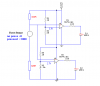
This is my circuit i try to design use UA741 and 1 Xnor and 1 And gates...

**broken link removed**

The Xnor is for the 3V and the And gates is for the 3.5V...

When force is apply to the sensor, there will be a volt at the Ain...I tested the range is 0V to 5V...This is the link of the Force Sensor...
Phidgets Inc. - Unique and Easy to Use USB Interfaces

Sorry for my bad english....as suddenly my teacher only give me a block diagram and ask me to design a circuit...I try to design it but i not really very sure is it going to work..>.< Can someone help if see...Pls tell me where i go wrong...Wish to learn from my mistake....Thank You...
 
Is the 741 a single supply op amp? Try using both a positive and a negative voltage on the 741. If you don't have a negative voltage supply, then try an LM 358 op amp, or one that only requires a single power supply pin.
 
Sorry....I dont really know what you are saying...Can you explain further?...>.<

The 741 may require both a +5 volt supply and also a -5 volt supply to work correctly. It looks like Pin 7 is +5 and Pin 4 is -5.

**broken link removed**
 
Sorry....I dont really know what you are saying...Can you explain further?...>.<

hi,
You have the 741 wired as a comparator, that means the output will be high or low, never halfway.

Because the 741 is a very old amplifier it has a poor specification.

With a single supply the output never go right down to 0V, more like +1V
and when high, not +5V , but about +3V.

So the circuit will not work as you expect at 3V and 3.5V input.. :)
 
You would need to use two comparators. One to detect above 3 and one to detect above 3.5. From what eric says you don't need a negative supply.
 
>.<....Eric got all the guess correct...But the main problem is i dont really know how to make 1 detect above 3 and another to detect above 3.5..As like Eric say...my circuit have problem already...Can anyone teach me how to edit my circuit..>.<''
 
>.<....Eric got all the guess correct...But the main problem is i dont really know how to make 1 detect above 3 and another to detect above 3.5..As like Eric say...my circuit have problem already...Can anyone teach me how to edit my circuit..>.<''

hi,
Do you have two 741 amplifiers.?
 
Yup....the school provide me 8 of them...as im trying to build a circuit to help the wall-climbing robot...>.<
 
Yup....the school provide me 8 of them...as im trying to build a circuit to help the wall-climbing robot...>.<

ok,

You need one 741 to detect 3V input and the other 741 to detect 3.5v.

The gates on the 741 output are not required.

I have just checked a 741 [the only one I have left from the 1970's!] and the best outputs I can get are +1.7V when low and +3.9V when high.

Can you design these two comparators yourself.. give it a go and post what you design and we will help you thru it.:)
 
**broken link removed**
My latest design...The bottom comparator Vref is around 3V and the top Vref is around 3.5V...im using circuit maker to test out the circuit as my house cant affort expensive device for me to use..>.< If the circuit can work...i will try out once i reach school....From the circuit i found out that i have to get the right LED because i saw some site, different LED have different If...correct me if im wrong...So is there a way to prevent this from happening??
 
The ua741 is output current limited to between 10 and 40ma of current, with a normal value of 25ma. 5 volts will drive any LED in existence that I know of, so even if you omit the resistor if the LED can sustain 25ma's of current it will be fine. No matter what LED you buy all you have to do is use a resistor to limit the current if it needs to be bellow 25.
 
hi woon
This from the link, what are the units.??? 0 when no force and 1000 when forced.?? is it ohms.?

The 1106 reads 0 when no force is applied. As force increases on the circular button the value increases towards 1000.

It is intended as a user input device (i.e recognizing that someone is pushing a button).

The 1106 is not accurate enough to be used as a weight measurement device and is not designed to have force applied constantly over time.

Have you any other data for this sensor.?
 
Last edited:
By using the circuit maker, the current at the output on the 3V comparator is about 12mV + and the 3.5V comparator is also 12mV+..so may be i have to lower the resistor...Also i try the force sensor using meter, when no force is apply its 0Ω but when force is apply its shoot up to 1.2kΩ...when hold there about some time the resistance drop....to about 200Ω+..sorry...cant really provide much info because the school bought it from that company..i saw the site at the bottom of the PVC board...
 
Last edited:
By using the circuit maker, the current at the output on the 3V comparator is about 12mV + and the 3.5V comparator is also 12mV+..so may be i have to lower the resistor...Also i try the force sensor using meter, when no force is apply its 0Ω but when force is apply its shoot up to 1.2kΩ...when hold there about some time the resistance drop....to about 200Ω+

OK,
Look at this sketch.

When using simulators you may not get the correct readings from the 741 outputs!

I have just done a test circuit and the RED led with a 100R goes from very dim [off] to bright [on]
 

Attachments

  • circuit2.png
    circuit2.png
    5.5 KB · Views: 155
Thank for all the help....I will do it when i reach school at the morning...If meet any problem i will post up...Hope u guy wont get scare away by me...>.<
 
Thank for all the help....I will do it when i reach school at the morning...If meet any problem i will post up...Hope u guy wont get scare away by me...>.<

Just do your best, we dont scare that easily..:)
 
AHHHHHHHHHHHHHHHHHHHHHHHHHHHHHHHHHHHHHH!!!!!!!!!!!!!!!!!!!!!!!!!!!!!!!!!!

Okay. I'm just being dramatic now.
 
A lousy old 741 might not work with a supply as low as 5V because the input common-mode range is a max of 4V above its negative supply voltage and 4V below its positive supply voltage. Then some will barely work with an 8V supply and still work with a very narrow input voltage range with a 10V supply.
It is spec'd only with a 30V supply.
 
Thank a lot to u guy, u all saved my life...Today the teacher come and check on the circuit and the teacher say it was good job...But the output of the 741 will be taken off as its going to the input of the mircocontrollor..At the same time the teacher gave me some problem or question..1 of them im still dont really know why...Teacher ask that when the force sensor (Ain) is lower than the Vref the output didnt went to 0..Also when its go higher then Vref its not going to 5V...I was stun when teacher as me that question..When lower than the Vref, for the 3V detect..The voltage at the output was 1.84 and the 3.5V detect was 1.54..When higher than the Vref, for the 3V detect the voltage go to 2.01V..and the 3.5V detect go to 4.85V (for the 3.5V i think should be ok)...Do u guys know why?..Also i using 2 different IC...1 is HA17741 and the other 1 is UA741CN....
 
Status
Not open for further replies.

Latest threads

New Articles From Microcontroller Tips

Back
Top