Continue to Site

Welcome to our site!

Electro Tech is an online community (with over 170,000 members) who enjoy talking about and building electronic circuits, projects and gadgets. To participate you need to register. Registration is free. Click here to register now.

  • Welcome to our site! Electro Tech is an online community (with over 170,000 members) who enjoy talking about and building electronic circuits, projects and gadgets. To participate you need to register. Registration is free. Click here to register now.

Need Help

Status
Not open for further replies.

J_Dearth

New Member
Hi,

I am very new to the electronics field and am working on a project. I have been surfing the internet for almost three weeks trying to figure this out and have spent over $200 at radio shack on parts and components that are not getting me what I want. (I am sure you are all rolling your eyes at the mention of radio shack but that is right now the only place I can think of to get electrical components). I keep finding my way back to this forum in my search so you all must know what your talking about.

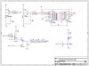
I am needing to wire a set of 10 LED's so that when I hit a switch one light turns on, then when I hit the switch again the second as well as the first light come on, and so on and so forth until all 10 LED's are lit. I also need there to be a second switch that will allow me to shut off the LED's in reverse order when that switch is hit. So in short I would like to push a button and make LED's light up in sequence and be able to shut them off with the push of a different button.

If this is too much non-tech talk I am sorry but I didn't want to appear like I was trying to talk about something like I knew what I was doing when I obviously don't. Any help would be greatly appreciated. I thank you all for any help you can give.
 
You can accomplish what you want with a up/down counter like the 4029 or the 4510. Check out this link:

4000 series CMOS Logic ICs

You can connect your pushbuttons to the clock input and with proper debouncing it will increment or decrement the output with each button push. You'll then need to decode the binary output with a BCD to decimal decoder IC something like this:

https://www.electro-tech-online.com/custompdfs/2009/12/74HC_HCT42_CNV.pdf

The outputs of the second IC can be used to turn the LEDs on or off.
 
You didn't say what happens if you press the extinguish button before lighting all LEDs (e.g. press ignite 5 times, then extinguish 10 times)..

If this will never happen, or you're happy with the lit LEDs shifting towards one end in this case: You can use a couple of shift registers with some simple RC delays on the data line. I could probably draw it up if that's what you're after.

If that's not quite what you're after, please say, and I might have to think about it; but it'd use some D-flip flops and some logic between each stage.
 
Hi all...

Regarding the first question in this thread...I also would like to ask about camera module.
I plan to make camera module which is embedded to DSP/microcontroller, has transmitter and receiver for capturing the image, has wireless communication and LED interface.

Is thr anybody who know where i can find such module? I have been searching in internet, but I could not get the complete package which I want.

Thanks in advance
 
Dougy,

I would like it to function in such a way that if I was to hit the extinguish button after only five lights being lit up that it would start to shut them down. In essence the ability to start shutting the lights off without the need for them all to be lit. I hope that answered what you needed. Thanks again for all the help.

As to VNE147,

Thanks. I am looking into how to use this 4000 series counter and the BCD decoder to make this work. Still a little confused as to how to make it all come together, but I hope I can figure it out. Thanks.

If I understand correctly, you want to start with all LEDs off. Then be able to push a button and turn them on one by one. So after one button press only one LED is lit, then after the second two are lit, the third press three are lit and so on. Do I have it right so far?

The second part that I want to make certain I understand is upon pressing the second pushbutton you would like all lit LEDs to turn off one by one in the reverse order that they were turned on and you want this sequence to occur from only a single button push? Is this correct? If so, the exact method I described will need some tweaking. How much of a delay would you want in between each LED going out after pushing the second button?
 
Last edited:
That sounds pretty much correct. The only thing I think might be different is that I would like the second push button to work identical to the first with the excetio that it is shutting them off rather than turning them on. So I would like to have to push the off button just as many times as the on button to get the system back to original state. I hope that clarified. Thanks again.
 
So I would like to have to push the off button just as many times as the on button to get the system back to original state.

OK, that makes sense and will be easier to implement than the other idea. What do you want to happen if you push either button more than 10 times? For instance if you have 8 LEDs lit and you push the down button 8 times, there will no LEDs lit. What would then happen if you pushed the down button again?
 
Now that I understand better exactly what you're looking for I'll admit that Dougy probably has the better idea with using shift registers. You could probably use something called a Johnson counter although I'm uncertain if there are bi-directional Johnson counters available. I'll continue looking into it but it sounds like that if I can't figure it out, Dougy has got you covered. Something that wasn't mentioned so far would be the microcontroller option. This would probably be the cheapest approach and wound definetly result in the lowest part count. However, it would require a bit more "getting up to speed" if you're very new to electronics.
 
Last edited:
OK. Sorry, as I've no idea what the application is, i can't just make assumptions (yes more questions ;) ).

In the case that you press ON 5 times you get:
1000000000
1100000000
1110000000
1111000000
1111100000
Now you press OFF 3 times for;
0111100000
0011100000
0001100000
Now you press ON 4 times for _____?? (please fill in blank)
My guess might be:
1001100000
1101100000
1111100000
1111110000
 
I'd like to offer a totally different method of making the lights light up in turn.

You could use a 10 position rotary switch, with a knob, and make it so as the turn the knob the leds light up in sequence, then turning the knob backwards makes them go out in sequence. Same visual effect, just as easy to use, and a heck of a lot easier to make. You just need the rotary switch and some diodes.
 
Ooops... I totally misread the original question. So the leds ignite from the left and extinguish from the right... That is a simple application of a bidirectional shift register. I'll draw you a schem later on.
 
What you have described is known as a Johnson Counter. There are neat applications of this circuit in almost all branches of electronics.

The big problem, as I see it, is that you want 10 lights. 8 lights would have been much easier. It really need to be ten?

The first and cheaper solution that jumps to my mind is using a bidirectional serial-in/parallel-out shift-register and wire it as a Johnson counter with a tiny logic at the fedback output to make it stop counting when it gets to ten. If you wanted 8 lights, you could use either the 74HC299 or the 74HC323 (they actually do much more than you need, but the simpler shift-registers are hard to find and these are cheap enough, less than a dollar each). To drive the 10 lights you want, you'll need to attach another 4-bit serial-in/parallel-out shift-register (perhaps the 74HC194, but I don't remember if it has parallel outputs).

The solution proposed by vne147 is a good one, but I don't see how you could transform the output of a BCD counter in what you need (10 bits) in a simple manner. If you know how to do that, using the counter as vne417 said is much easier and less bug prone.

Castilho
 
I could just as easily do 8 lights rather than 10. I think if you could show me a way to do eight lights and make it happen I would be eternally grateful. Cost is not a factor, I would like this to work that is all. Also, just in case do you know the best location to get these components from? Thanks. Let me know what you come up with and I will work from there. Thank you again.
 
Someone could probably write a PIC program to do it with a cheap PIC 16F628 or similar. It's only 2 buttons and 10 LEDs.

I'd do it. In fact, for the cost of parts, shipping, and a little something extra that we'll both have to agree in advance is fair, I could send you a finished circuit that's ready to go. What part of the country to do live in? The only catch is I won't be able to ship it out to you until after the new year. If you're interested, PM me and we can work out the details.
 
My very first post so if I screw this up please take it easy. Years ago I worked with a circuit that did similar to what you are looking for. Strictly a TTL circuit and with a little modification may give you what you want. The circuit looks like this:

**broken link removed**

Hope that doesn't break the tables? The above circuit does have an error in the pinout of the 74154 chip:

The pin out of the 74154 chip in the above image is incorrect. This just came to my attention. Note that pin 14 is shown as common and again shows up as an output (Y12). Pin 14 of this chip is not common. Pin 12 is common.

The circuit provides an output that looks like this:

**broken link removed**

Now you only want 10 LEDs so you would change the 7400 pin 9 from pin 17 of the 74154 to pin 10. Also the LEDs light in sequence so to have them remain lit with 1, 2 3 etc you would need to modify the circuit. The existing circuit is driven by a 555 as a clock that you would eliminate and replace with a bounceless switch.

Overall with some modifications the above might work for you, then too it may not be what you want.

Ron
 
I live in Seattle, WA. I would definitely be willing to work something out to have this done. Let me know if you are inerested and what we would be talking as far as price and we can definitely make this happen.
 
I have just drawn a sketch of something I think might work.

But I don't give any warranties! ;) Try it at your own risk =P

There are a few parts of this circuit about which I feel a little messy...

1 - That crapy diode logic at the clock generating circuit (that prevents the circuit from counting up when the number ten is reached). I don't know if the diode drops won't interfere with the HC drops... I know, from my own experience, that ORing with diodes is not the wisest thing to be done (ANDs are so fine till now...).

2 - In order to use only three ICs, I have put there only three NOTs to generate the delay necessary to the shift magic work (the inputs S0 and S1 need to be in a stable state for, at least, some nanoseconds before the clock input goes from low to high. As these signals are generated by the same switch, it's necessary to delay the clock a little bit.) The set-up time of the S0 and S1 inputs indicated in the datasheet of the 74HC299 shows a worst case scenario of 100ns. The propagation delay of the 74HC14 is about 20ns... So... You should experiment with the circuit to know if it's reliable.

3 - The debouncing circuit may not work with the switches you buy. Experiment with the cap values until you are satisfied.


NOTES:
If someone could review this circuit, I would appreciate it. I don't want to suggest something that won't work. :p
I don't have the 74HC194, so I can't assemble the circuit at a breadboard here at home. From my personal experience, it's very difficult that a circuit works from scratch without any modifications.

EDIT: And it's a little bit late here in Brazil right now, it's practically Christmas Eve, so give me a break if I have made some stupid mistake :p

EDIT 2: Staring at the complexity of this circuits and the myriad of bug possibilities it has, I'm starting to think that's much better to play safe and use a microcontroller =). Discrete digital logic sucks hard. I tend to think that microcontrollers kill all the fun of electronics, but they are much simpler and more reliable...


Castilho
 

Attachments

  • 10-bit Johnson Counter.jpg
    10-bit Johnson Counter.jpg
    63 KB · Views: 559
Last edited:
Status
Not open for further replies.

Latest threads

New Articles From Microcontroller Tips

Back
Top