Continue to Site

Welcome to our site!

Electro Tech is an online community (with over 170,000 members) who enjoy talking about and building electronic circuits, projects and gadgets. To participate you need to register. Registration is free. Click here to register now.

  • Welcome to our site! Electro Tech is an online community (with over 170,000 members) who enjoy talking about and building electronic circuits, projects and gadgets. To participate you need to register. Registration is free. Click here to register now.

Need help with transistor switch (on at open switch)

Status
Not open for further replies.
Yet another alternative would be to drive the relay directly from the sensor but use a normally closed contact on the relay to drive the load. This has the disadvantage the the relay will be energised for most of the time thus consuming some power. Here is an explanation for baterdmutt's benefit. The normally closed contact on the relay will allow current to pass when there is no current passing through the relay coil. As the contact on your sensor is closed when it is not activated the relay coil will have current passing through it. This mean that the normally closed contacts on the relay will be in the open state so no current will pass to the load. When the sensor is activated its contacts open causing the relay coil to be de energised which means that the relay's normally closed contact will now be closed. The relay is behaving as the NOT gate you wanted to use.

Les.
Hi Les,
That was my first thought, but I don't have any N/O relays (lots of N/C ones). The relay would be energized almost constantly and I didn't like that idea. I thought I could use a latching relay but then I'd have to figure out how to send a signal to turn it back off. I just figure transistors would be simplest. Thanks for the idea though.
 
Just use any NPN transistor you have with a suitable voltage and current rating with a value of base resistor to positive supply to turn it fully on. (As already suggested.) Don't forget to put a diode across the relay coil to clamp the back EMF. You could even use a PNP transistor with the wiring changed to suit the reverse polarity.

Les.
Thanks
 
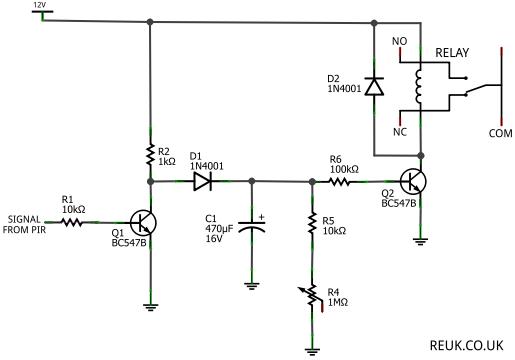
So I found this circuit and thought it would be perfect for what I need. I put it together on a breadboard and it always has a high output. So it's not inverting. In other words the relay is always on. The only difference is that I am using 2n3094 transistors, but I thought they should still work in this instance. Can anyone see what the problem is? Help!
pir-sensor-timer-circuit2.jpg

I should add that this is supposed to go high when there is a signal from the PIR and stay there from 5-75 seconds based on the setting of R4. But when I connect it it goes without a signal and stays there.
 
With nothing connected to the input (Left hand end of R1) transistor Q1 will not be conducting so its collector will be at near +12 volts. As a result of this Q2 will turn on (As it's base is connected to about +12V via D1 ans R6.) As Q2 is conducting the relay is energised. If you connect your PIR (Remember that it's contacts are normally closed.) between the left hand end of R1 and +12 volts then Q1 will be turned on which will cause Q2 to be turned off. In all of the methods already suggested the transistor base (Or gate in the case of a mosfet.) was being pulled towards + 12 volts by a resistor but the PIR contact would be connected between the base and 0 volts shorting out the base emitter junction (gate and source in the case of a mosfet.) thus preventing the transistor from conducting until the PIR was activated causing it's contacts to open.

Les.
Thanks Les, but if I connect +12 to the left side of R1, then it should then cause (ultimately) the relay on the schematic to open (after any delay caused by (R4)), and it doesn't. If you are positive the schematic is correct then I guess I'll try again.
 
What is the coil resistance of your relay? 700 ohms?
The value of R6 is so high that the relay coil resistance must be 4700 or 10000 ohms which is not possible. For the relay to turn on then Q2 must be a darlington transistor or a Fet.
 
What is the coil resistance of your relay? 700 ohms?
The value of R6 is so high that the relay coil resistance must be 4700 or 10000 ohms which is not possible. For the relay to turn on then Q2 must be a darlington transistor or a Fet.
The relay is turning on. It won't turn off. And yes it is a normally open relay so it's on because it's being pulled on.
 
The 100k resistor R6 has a voltage across it of 12V - 0.7V - 0.7V= 10.6V then it provides a base current to transistor Q2 of 10.6V/100k ohms= 106uA.
The datasheet for the 2N3904 transistor and almost all little transistors say that for it to saturate properly then the base current should be 1/10th the collector current. Then the relay coil must use only 106uA x 10= 1.1mA and have a resistance of 12V/1.1mA= 11k ohms.
Your transistor turns on and stays on because it is shorted or has its pins mixed up.
I think you are right. I have a bunch of other 3904's so I'll try again with new ones.
 
I don't get it, the circuit in post 24 with a NC sensor input to COM has exactly the same logic as the 2n7000 ver with only four components, incl the relay and diode.??
Max.
 
R4/5/6 have such a high combined resistance that transistor base leakage current might be enough to prevent the relay dropping out.
 
I don't get it, the circuit in post 24 with a NC sensor input to COM has exactly the same logic as the 2n7000 ver with only four components, incl the relay and diode.??
Max.
But I don't have any 2n7000 so I'm using the 3904. Otherwise I'd do the one you recommended.
 
R4/5/6 have such a high combined resistance that transistor base leakage current might be enough to prevent the relay dropping out.
I think that would be by design. R4 and C1 are to delay the relay from turning off for 5-75 seconds. I think it's right because I think it's working for me now the way it's supposed to. I haven't had much time to test it though to make sure.
 
Status
Not open for further replies.

New Articles From Microcontroller Tips

Back
Top