Continue to Site

Welcome to our site!

Electro Tech is an online community (with over 170,000 members) who enjoy talking about and building electronic circuits, projects and gadgets. To participate you need to register. Registration is free. Click here to register now.

  • Welcome to our site! Electro Tech is an online community (with over 170,000 members) who enjoy talking about and building electronic circuits, projects and gadgets. To participate you need to register. Registration is free. Click here to register now.

Need help with HBridge Designs

Status
Not open for further replies.

RussianKid

New Member
Hi!

I am currently researching H-Bridges to drive bipolar stepper motor using a PIC (PIC18F2550 to be precise). Since this is in the context of a CNC machine/milling machine conversion, the drive system has to be quite (very) powerful (60V maximum, at variable currents - 12A maximum).

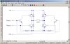
I have done and prototyped most of the parts of this, however, there is one thing I do not quite understand. As far as I understand, a normal H-Bridge is as in the 'Normal H Bridge.jpg' attachment, however, especially in applications involving MOSFETs, I have increasingly encountered H Bridges where the transistors (or MOSFETs) are all the same polarity (the 'Abnormal H Bridge.pdf' attachment exemplifies one such application). That is by no means an isolated example, as the same is found in RC car electronic speed controls.

More specifically, I do not understand how the transistor/MOSFET to the emitter/source of which the load is connected can switch on/off: surely if the vast majority of the voltage drop occurs on the load, then the potential difference between the emitter/source and the base/drain disappears, thus stopping the transistor/MOSFET from opening? (the simplified version is demonstrated in Simplified.jpg).

I am specifically interested in how H Bridges which all use the same polarity work, as my chosen MOSFET source OnSemi has N Channel MOSFETs with a minimal internal resistance of 9.5 mΩ, but P Channel of 80 mΩ, hence, using an N Channel MOSFET is not only cheaper, but also reduces heating during operation. The data sheet of the specific MOSFET I have in mind is also attached.

Thanks in advance, and sorry for the long post!
Alex
 

Attachments

  • Normal H Bridge.JPG
    Normal H Bridge.JPG
    55.1 KB · Views: 523
  • Abnormal H Bridge.pdf
    231.3 KB · Views: 290
  • NTB75N06-D.pdf
    72.8 KB · Views: 283
  • Simplified.JPG
    Simplified.JPG
    51.7 KB · Views: 252
I can understand you wanting to go for N-channel but 12A through an 80mΩ MOSFET only drops 960mV which is nothing compared to 60V.
 
Last edited:
It's more the heat dissipation that concerns me:

Since:
W = I² * R
W = 12A² * 0.08Ω = 11.52W of heat?

I seem to remember that with 9.5 mΩ this drops to something like 1.5W, a much more manageable amount.

Then again i may have gone wrong somewhere :(
 
You can use an N-channel if you can supply the gate with 70V.

By the way are you using BJTs or MOSFETs because according to your schematics you're using BJTs?
 
Yes, I realize now, I should have used MOSFETs in my schematics to save confusion. They're supposed to be MOSFETs, sorry.

In terms of 70v, can the MOSFET handle that, in light of the fact that the datasheet states that the gate can have ±30v maximum?
 
Also, to open the MOSFET needs there to be a lower voltage at the gate than at the source, in simpler terms, a current needs to flow in the same direction as the arrow?

Applying 70v to the gate would mean the voltage is higher at the gate than that at the source, hence the MOSFET wouldn't open?

Also found this:

https://www.electro-tech-online.com/threads/high-power-h-bridge.26112/

Another example of an all N Channel bridge.

I am still confused in terms of a schematic as to how to interface to a PIC though.

P.S. Perhaps I was vague again, but the 60V is a maximum ration, I intend :)rolleyes:) this to work with any voltage up to 60.

Thanks for all the help so far
 
Also, to open the MOSFET needs there to be a lower voltage at the gate than at the source, in simpler terms, a current needs to flow in the same direction as the arrow?

Applying 70v to the gate would mean the voltage is higher at the gate than that at the source, hence the MOSFET wouldn't open?

Also found this:

https://www.electro-tech-online.com/threads/high-power-h-bridge.26112/

Another example of an all N Channel bridge.

Are you talking about N-Channel or P-Channel? When using all N-Channel fets, you need a VGS that is greater than the supply voltage in order to turn the upper fets on. The IR21844 ICs that I used in that high power hbridge have a built in boost converter to generate enough voltage above the supply to turn on the upper fets.

I am still confused in terms of a schematic as to how to interface to a PIC though.

P.S. Perhaps I was vague again, but the 60V is a maximum ration, I intend :)rolleyes:) this to work with any voltage up to 60.

Thanks for all the help so far

In my schematic there, all you have to do is connect the PWM output of the PIC to R18.
My circuit will always be applying current to the motor. (When at 50% duty cycle, it will drive the motor forward 50% of the time and backward 50%.)

I only ran mine up to 45V, but it only depends on what the fets are rated for.
 
Also, to open the MOSFET needs there to be a lower voltage at the gate than at the source, in simpler terms, a current needs to flow in the same direction as the arrow?
To open (turn off) a MOSFET you normally put the gate at a voltage near the source voltage. The only current that needs to flow it that required to discharge the gate capacitance (which can be rather large for high current MOSFETs). Thus to rapdily turn a MOSFET on and off (which is usually desired in a switching application to minimize transistor dissipation) you need a gate driver that can rapidly charge and discharge the gate capacitance.
 
In terms of 70v, can the MOSFET handle that, in light of the fact that the datasheet states that the gate can have ±30v maximum?
Both gate and drain voltage maximums are referenced to the source terminal. Thus you can apply more voltage to the drain-source then the the gate-source. But this is not usually a problem.

For example, if an N-channel MOSFET is in the top of the bridge, you may be applying 80V (to ground) to the gate but, since the transistor is on at that point, the transistor source is near 70V, so the gate-source voltage is only 10V, well below it's gate-source limit.
 
yes, I understand now (i think), thanks

it would also appear that the IR21844 driver you used is more than suitable for my application, however, it is rather pricey (and I definitely don't need the 600v it offers)... can anyone suggest an alternative which would be:

- PIC (18F2550) compatible
- support 60V
- be a half/full bridge driver
- cost say, <=$1

i'll have a look on RS and the major semiconductor sites as well

Thank you all
 
**broken link removed**

just to confirm, that can't be used with a 60v setup can it? although the 15v it requires may be enough to drive the gate?

Just thought i'd double check because its very cheap, and the compact 8 pin package to drive 2 MOSFETs would be very nice.
 
Last edited:
According to my understanding of the circuit, the voltage output to the gates of the MOSFETs is no greater than the supply voltage (and less a diode drop for the bootstrapped high side). Thus you would need MOSFETs that carry the required current at a 4V or so if you operate it from the 5V PIC supply voltage. Those may not be readily available for your 12A, 60V application. So you may still need an additional power supply to power the bridge (they show 12V in the data sheet).
 
That HIP4082 looks like it would work and its not too expensive either. My H-bridge project got expensive pretty quick once I started blowing fets and those IR21844's.

Thus you would need MOSFETs that carry the required current at a 4V or so if you operate it from the 5V PIC supply voltage. Those may not be readily available for your 12A, 60V application. So you may still need an additional power supply to power the bridge (they show 12V in the data sheet).

Looks like this chip is able to handle a 5V inputs for any VDD. (See VIH and VIL on pg 4: The chip sees any input greater than 2.5V as a logic high and anything below 1.0V as a logic low).
Even if the chip couldnt handle 5v inputs, you could just use a single 12V supply and use a 7805 VReg to make the 5V for the PIC. The PWM output of the pic would have to drive an open collector transistor to get the pwm signal to +12V.

Oh yeah, I'd strongly recommend adding overcurrent protection. I added it to mine after nearly catching my breadboard on fire. I had just got it working and was paying attention to the motor when it stopped. I look over and see a big cloud of smoke coming from the breadboard. Turns out it was a mosfet failure and it shorted my 45V bus. Heres a pic:
**broken link removed**
 
Yes, however unfortunately, using a 5V supply voltage would not open the MOSFETs fully, and not achieve their best Rds (unless the driver contains an internal voltage multiplier, which is unlikely), so I'm just going to have a separate voltage supply for the FETs, triple the 5V PIC voltage and regulate that down to 12V.

I have pretty much resolved the issue at hand, however I have one final question: say I drive the FET gate using, say 12V, can I then get the FETs to switch lower voltages from the 'power' PSU? In other words, can the logic power supply have a higher voltage than the power supply? Is the lower limit related to the FET gate threshold voltage in any way?

In terms of current protection, I am definitely going to have Op Amp based current monitoring, which should one FET fail, the PIC can at least close the others to try to prevent further damage. Also, I am going to have temperature monitoring, however only of the main heat sink, not each individual FET.

While the HIP4082 and similar are indeed very nice, at >$4.50 each, they're a bit expensive for me. (which means I've changed my mind 3 times now sigh, indetermination :rolleyes:)

And I'm really hoping I wont end up needing such massive heat sinks :)
 
Last edited:
Yes, however unfortunately, using a 5V supply voltage would not open the MOSFETs fully, and not achieve their best Rds (unless the driver contains an internal voltage multiplier, which is unlikely), so I'm just going to have a separate voltage supply for the FETs, triple the 5V PIC voltage and regulate that down to 12V.

Why not just use a 12V supply and regulate it down to 5V?

I have pretty much resolved the issue at hand, however I have one final question: say I drive the FET gate using, say 12V, can I then get the FETs to switch lower voltages from the 'power' PSU? In other words, can the logic power supply have a higher voltage than the power supply? Is the lower limit related to the FET gate threshold voltage in any way?

I believe that would put the mosfet in the linear region. The fet will act like a resistor and make tons of heat.
https://upload.wikimedia.org/wikipedia/commons/d/d7/IvsV_mosfet.png

While the HIP4082 and similar are indeed very nice, at >$4.50 each, they're a bit expensive for me. (which means I've changed my mind 3 times now sigh, indetermination :rolleyes:)

And I'm really hoping I wont end up needing such massive heat sinks :)

Intersil offers free samples... **broken link removed**.
You have to register with them and everything. They only let you order 2 of any single chips, 4 chips total. The HIP4080-Hip4082 chips are all pretty similar though, so you can get 2 each of those.

If the FETs and heatsink get too hot, you can always add a fan to it.
 
I was under the impression that the MOSFET needed 10v gate voltage to achieve optimal Rds, however if 5v is sufficient, it makes absolutely no sense to use 12v at all...
 
Status
Not open for further replies.

Latest threads

New Articles From Microcontroller Tips

Back
Top