Continue to Site

Welcome to our site!

Electro Tech is an online community (with over 170,000 members) who enjoy talking about and building electronic circuits, projects and gadgets. To participate you need to register. Registration is free. Click here to register now.

  • Welcome to our site! Electro Tech is an online community (with over 170,000 members) who enjoy talking about and building electronic circuits, projects and gadgets. To participate you need to register. Registration is free. Click here to register now.

Need help with building current to voltage converter!!

Status
Not open for further replies.

erikj

New Member
Here is a brief of what I must do. Could anyone help me with a circuit that will work and the components that I will need please!

Design Project. Due date: 8 November 2013
Background

In factory instrumentation, process parameters such as pressure and flowrate are measured,converted to electrical signals, and sent some distance to an electronic controller. The controllerthen decides what actions should be taken. One of the main concerns in these systemsis the physical distance between the sensor and the controller. An industry standardformat for encoding the measurement value is called the 4–20 mA standard, where theparameter range is linearly distributed from 4 to 20 mA. For example, a 100 psi pressuresensor would output 4 mA if the pressure were 0 psi, 20 mA at 100 psi, and 12 mA at 50 psi. But most instrumentation is based on voltages between 0 and 5 V, not on currents.
Problem
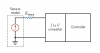
The circuit in Figure1is a very accurate model of our situation. The wiring from the sensor unit to the controller has some resistance Rwire. If the sensor output were a voltage proportional to pressure, the voltage drop in the line would cause measurement error even if the sensor output were an ideal source of voltage. But, since the data are contained in the current value Rwire, does not affect the accuracy at the controller as long as the sensor acts as an ideal current source.
Figure 1. Sensor to controller connection
Design a current-to-voltage converter that will output 0 V at 4 mA and 5 V at 20 mA.
Write a report describing your design.
Tip – Use Opamps
 
Design Project. Due date: 8 November 2013
And you were given this when???

Tip – Use Opamps
You already have the answer... Google "current to voltage using opamps" and you'll get quite a few hits..
 
I cannot open your attachment.

A simple resistor converts a current into voltage. Unlike resistance in the wire connecting the sensor to the monitor, when you use a sense resistor at the monitor, you can measure the voltage drop.

John
 
Post a circuit diagram or a description of your version of the Current to Voltage converter.
We can then give you some hints/clues on how to proceed.
E
 
Post a circuit diagram or a description of your version of the Current to Voltage converter.
We can then give you some hints/clues on how to proceed.
E
This is the basic diagram that came with the assignment
 

Attachments

  • dddd.png
    dddd.png
    3.9 KB · Views: 314
Hi,
Basically what is needed is a 249R precision resistor connected into the 4-20mA current Loop.
One side on the resistor is connected to 0V/Common, the other end then will have, due to a 4mA thru 20mA flowing thru the 249R, a voltage of~ +1V thru ~+5V.

This a is a 1V to 5V Span for a 4mA thru 20mA current in the loop.

Your design will have to cancel/remove the +1V, so that the Span becomes 0V thru +4V,, also it will also have to amplify this to 0V thru +5V.

I would consider a dual OPA powered by say 9Volts, one half of the OPA would be used for the generation of a stable +1V offset voltage and the second a low gain amplifier.

From these hints/clues design your circuit and post it here and we will check it out.
Is important that you attempt the design and show us what you have done yourself.
E
 
Basically what is needed is a 249R precision resistor connected into the 4-20mA current Loop.
Why 249 Ohm?
250 Ohm 0.1% (or 0.01% if you can afford) resistors are commonly used to give an accurate 4-20mA to 1-5volt conversion, and would be found in any instrument workshop.
249 Ohm? I doubt it.

JimB
 
249 Ohm? I doubt it.
I bought and used 249R 0.1% precision resistors for many years in just this type of application.
As the OP has to cancel the Voffset and also amplify the signal across the resistor, the value is not critical, so I suggested a resistor which will get the job done.
https://uk.farnell.com/vishay-dale/rn55c2490bb14/resistor-metal-film-249-ohm-125mw/dp/4674303
E

Take your pick from this extensive range
https://uk.farnell.com/jsp/search/browse.jsp?N=2031 215514&Ntk=gensearch&Ntt=249 ohm resistors&Ntx=mode matchallpartial

In case the OP decides on a 243R as suggested by Ian, post #5, link
https://uk.farnell.com/jsp/search/b...rch&Ntt=243+ohm+0.1%&Ntx=mode+matchallpartial
 
Last edited:
As the OP has to cancel the Voffset and also amplify the signal across the resistor, the value is not critical
True.

For whatever reason I had not realised that 249 Ohm was such an available value.

However, from a practical testing point of view, a 250 Ohm resistor makes life much easier when trying to measure the input current.
1v = 4mA
2v = 8mA
.
.
5v = 20mA

Whereas for a 249 Ohm resistor

0.996v = 4mA
1.992v = 8mA
.
.
4.980v = 20mA

To my simple mind, the 250 Ohm resistors make life easier.

JimB
 
I guess its just a case of what we get used too, I have a quantity of 249R left over from when I used to make this kind of unit, [ I suspect Ian with the 243R is the same.?]
I have a comprehensive stock of components left over from when I retired my company, but not any 250R's funnily enough. :)

In practice when using OPA's any value from 100R thru 1K will do, in hindsight I should have stated this to the OP.

Eric

NOTE: Ensure that with a higher value load resistor that there is a sufficient overhead voltage for the remote driver.
 
Last edited:
Hello,

I dont think there is much difference between using a 250 Ohm and 249 Ohm (about 0.4 percent which is less than one half percent) but yes the price and availability is sometimes important too. I have often used slightly off target resistor values so that i could get them cheaper or faster.

Now let me interject my own value <chuckle>

If i understand this problem correctly, my idea would be to use a 312.5 Ohm resistor (ha ha, much different). Why this value? Well, if he really does need a 0v to 5v signal span then he can get that *span* without amplification using that value, then all that is left to do is subtract the offset voltage that appears at 4ma which comes out to 1.25v. So that would be all that is left to do, and that would result in a range of 0v to 5v without the need for amplification.

Of course this assumes that the current being measured is backed by a voltage that can go high enough to supply 6.25v at the 312.5 Ohm resistor, and still provide the voltage for the line resistance voltage drop. This has been an assumption all along for the other ideas too though, except the voltage with a 250 Ohm resistor can be a bit lower like around 5v plus line resistance voltage drop. So this partly depends on the system output voltage and line drop.

If the line drop is significant we may have to rethink this anyway. So a question that comes up is just what is the line resistance and what is the max output voltage of the source.
 
hi Al,
Why I dont disagree with your maths I would say in a real life situation the designer would have to consider how the 'user' is going to make use of this 1.25V thru 6.25V.
As you say, he has to cancel out the +1.25V offset in such a way that he does not effect the 312.5R loading.
Also he would have to consider any loading to the 312.5R [ and offset cancelling circuit] by the load the 0V thru 5V is driving.

Eric
 
Hi Eric,

Yes i agree. There has to be a little more signal processing involved, but i thought that was the case with any value resistor or any other method too. My idea was just to be able to eliminate the amplification, that's about it. The offset still needs to be removed as you said. With a 1v to 5v range, the offset needs to be removed and also amplification, assuming he really needs 0v to 5v and can not live with 0v to 4v for example. He might even be able to live with 1v to 5v i guess.

I also agree about the loading, and because i dont know what load he has in mind and i also dont know the voltage capability of the sensor shown in the simple drawing, i need more information in order to determine the best (or one of the best) implementation(s).

Perhaps he can supply more information for us.

I was going to check price and availability on the 249 Ohm and 250 Ohm resistors but i had to do something else. I'll check that now though just to see the difference from one supplier.
Ok, checked: they have 249 Ohm but they do not even have 250 Ohm, which surprised me a little as they are a big supply outlet. So buy a 249 and a 1 ohm and connect in series (ha ha).

Smiley's dont seem to work all the time with the new software.
 
249 Ohms is a standard E-96 value. The next higher E-96 value is 255 Ohms.

The next higher series is the E-196 series. In it the close values are 249 and 252 ohms.

250 Ohms is not a standard value in either series. That doesn't mean that it's not available, just that you'll probably have to have it made special and be willing to pay through the nose. And probably have to buy many tens of thousands of parts.

As for putting a 1 ohm in series with a 249 ohm, remember the effect of component tolerance. A 1% 249 ohm resister could actually have a value as high as 251.49 ohms. Also, each resisters in the system adds it's own error due tho the same tolerance effect. And it's not only resisters that can add errors. Voltage and current references, A2D accuracy, operating temperature, etc. will also affect the precision of the final system.

So, if you really need a tight tolerance through the system, you're better off adding some sort of trimming to the system, and calibrate it with some precision measurement equipment.

Of course, for a homework assignment, you can probably get by with using any calculated value you want to put down, even if you cant actually buy the part.
 
Hello Chris,

I dont know about you but i was kidding when i said buy a 249 ohm and a 1 ohm and connect them together. Since you brought it up though, nobody ever said we had to use 1 percent resistors either. Using 0.1 percent tolerance resistors might actually work for that making the max resistance about 250.25 ohms but probably much better than that near room temperatures.

I seriously doubt that he needs a close tolerance like that anyway, that's why i was kidding about that, but in the old days when we used carbon resistors we were able to file a small groove into the resistor body with a "V" shaped file. That removed some of the resistive material and caused an increase in resistance. That allowed some way to adjust the value a little although decreasing the power rating somewhat also.
 
hi Al,
When using OPA's with a current loop resistor, the important factor is the stability of the resistor, not the manufactured tolerance.
Thats why I suggested a precision resistor of 249R 0.1%

As you know the old carbon resistors could be filed/tweaked to achieve a required resistance,
but the resistance would change due to the slightest temperature change.:arghh:

Eric
 
Hi Eric,

Yes i was just kidding about the 249+1 ohm resistors, and did not think it ever had to be that accurate, and i was agreeing with you that 249 would be the best choice because it was widely available and accuracy was not THAT critical.

And i also agree that carbon resistors are frowned upon these days and can change much more with temperature and age. That was way back when carbon resistors were more popular and hobbyists could tweek their resistors without using a pot or something. I believe this also might also have been published in Popular Electronics way back, if you remember that old magazine. I used to have stacks of these mags from year ago. The other part was to coat it with varnish or some other coating approved for electrical work. It was actually fun to do in a way, but we had to be careful not to dig too deep into the body or else the power rating would decrease too much with a 'hot' spot in the center. What was nice is that you could trim the resistor to any value you needed, and for some apps the temperature did not change too much anyway so it worked out ok.
I also think it can be used on metal film, but never tried it on that type.
Here's a quick link but im sure there are others, possibly better:
http://www.all-electric.com/schematic/res_trim.htm
 
MrAl,

Yes, I know that you were (probably) kidding, but some newbie will read that from a Well-Known Member and assume that that is a standard procedure in the industry.

And I have seen it done by people who don't understand the issues. One circuit I remember seeing had three 5% resisters in series to get to some exact value, even though the delta from tolerance of the largest value in the string was much greater than the actual value of the smallest.


I've never done the file trim method with carbon comp resisters, but have heard of it. Another thing I was told about carbon comp resisters, was that a 10% part was almost guaranteed to be at least 5% off. They didn't really make 5% parts, they just tested all of the resisters and sorted them based on how close they were to target.
 
Status
Not open for further replies.

Latest threads

Back
Top