donovanbuck
New Member
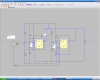
I have been trying to build a circuit that will replicate the action of an optical encoder. I need to be able to alternately fire two small relays to simulate the clockwise or counterclockwise rotation of a notched HVAC fan speed control. It would be nice to operate this circuit with only two momentary buttons, one each to simulate cw or ccw rotation. I suspect a 555 or 556 timer type circuit should work but I am stuck on how to initially start the astable process to make it start with one relay or the other. According to the spacing of the notches on the knob passing through the optical encoder is would be a 50 percent duty cycle. I hope I have provided enough info for someone here to point me in the right direction or to a link for the type of circuit I am trying to build. I appreciate any help I can get. Thank you.