Continue to Site

Welcome to our site!

Electro Tech is an online community (with over 170,000 members) who enjoy talking about and building electronic circuits, projects and gadgets. To participate you need to register. Registration is free. Click here to register now.

  • Welcome to our site! Electro Tech is an online community (with over 170,000 members) who enjoy talking about and building electronic circuits, projects and gadgets. To participate you need to register. Registration is free. Click here to register now.

Need help with a sequential LED circuit using 4017 & 555

Status
Not open for further replies.

twisted_iggy

New Member
i need to do this for a school project and have ran out of ideas on how to go about getting it done, im still a beginner, so any diagrams that could help me out wud b great

the materials i can use are
4017 cmos chip
555 cmos timer chip
10 LEDs
JK Flip Flops

i want it to run on 12VDC

it must flash back and forth
(9-8-7-6-5-4-3-2-1-0-1-2-3-4-5-6-7-8-9 and so on)

thanks
 
While we won't do your project for you, I know a great many of us would like to help point you in the right direction, however that is impossible without more knolwedge on your current ideas. You say you have "run out of ideas" as to how to finish this project, so presumably you had some ideas? Why don't you share them, so we can help critique your plan of action.
 
basically ive figured out that i can run the led's in one direction

01234567890123456789...

im trying to figure out how to flip around the wires to the LED's i guess, so that it will reverse the sequence that the led's flash in...using a jk flip flop (?).
 
well, there are two basic ways that i see to do this.

one would be to use a counter (instead of the 4017), what has the ability to count up or down, depending whether there is voltage on a particular pin.

the other would be to have two 4017 ICs that are all connected to the same LEDs, but one is connected in the reverse order.

As Gandledorf says, we don't want to do your project for you (what would be the fun in that?), but hopefully this has given you some ideas (its up to you to figure out how to make the 4017s run one after the other...)

Tim
 
yea i thought about using two 4017s, but teacher told us that its possible to complete the circuit using only one 4017 and one 555, so i was trying to figure out if anyone knew how that cud b done...but if worse comes to worst, then i guess ill haf to use two 4017s...oh, and if i use two, do i need a diode for each led to protect the other 4017 chip? or will the pulses from one chip not affect the other?, thanks for all your help
 
Put 5x2 switch to swap outputs 0 and 9, 1 and 8, 2 and 7, 3 and 6 and 4 and 5.
 
panic mode said:
Put 5x2 switch to swap outputs 0 and 9, 1 and 8, 2 and 7, 3 and 6 and 4 and 5.

hmmm, wuts a "5x2 switch"?, can i do that wit a flip flop?, or 4 flip flops?, or is that just not efficient?
 
"yea i thought about using two 4017s, but teacher
told us that its possible to complete the circuit using
only one 4017 and one 555, so i was trying to figure out
if anyone knew how that cud b done...
"

i am not at all sure it can be done with just those
chips.

If it can, i would be very interested to see how.

Regards, John :)
 
Your teacher is wrong. 4017 counts only forward (this is
"hardwired" inside chip).
If you want it reversible, you should use bidirectional
counter and use this to drive decoder.
Using fancy circuits with two 4017 counters or selector switches
it is possible to do the same but it is not worth effort.
If you ask me, I would use PIC16F84 and label it "555+4017"
as a joke. Using buttons you can select different pattern
or sequence.

Here is an interesting link
**broken link removed**

If you put 16F628 for example, you don't need external components
for oscillator and you have total of 16 I/O and if you multiplex them
you can get much more LEDs.

Bellow is what was meant by 5x2 selector switch. Actually you would need
10x2 to swap all 10 outputs.
 

Attachments

  • selector.GIF
    selector.GIF
    1.3 KB · Views: 2,497
Just a Thought?

I notice that you put in the tile of this post "Need help with a sequential LED circuit using 4017 & 555". Note the word "Sequential". Sequencial is usually meaning one way or in sequence, not ping pong, or bounce. Could you have understud wrong the project, becasue frankly, I can't see how using the materials listed you could do this knight rider effect. The only thing that throws me off is your jk flip flops. Anyway just a thought.
 
I think that your instructor just wants you to have the circuit count up,I am not sure though.In either case make sure that the clock enable pin on the 4017 in to ground.I just got done making a two led bank, double flasher on a pcb,and forgot this important pin.It will not work very well without it,and good luck..... :?
 
4017 & JK F/F up/down connections

Hi, twisted. You've had some time now to work through it, so I thought I'd post my 2 cents. niq_ro has the right idea, though it looks like the LEDs are drawn backwards.

A compact way to solve problems like this is with a small micro, as Panic pointed out. However, designing with micro's has a steeper learning curve than wiring up basic logic circuits, and may be outside the scope of your class.

the materials i can use are
4017 cmos chip
555 cmos timer chip
10 LEDs
JK Flip Flops

(In addition to these parts, you'll need some diodes or OR gates on the 4017 outputs)

Take a look at the schematic in this link for a solution using a 555 and two 4017's (the circuit shown has 9 outputs, not 10. The transistor is used as an inverter. Notice the diodes on outputs Q0 and Q8 aren't logically needed, they're probably included to match brightness levels among the LEDs.).

http://www.geocities.com/lemagicien_2000/elecpage/bounlite/bounlight.html

You can achieve a similar effect using a flip-flop in place of the second 4017. As others have pointed out, the 4017 can only count in one direction.

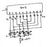
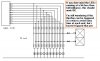
Simulating a bi-directional count on the 4017 (using all 10 outputs) requires an additional "state" bit. In the partial schematic shown below, a negative-edge triggered JK flip-flop is clocked using the Cout pin from the 4017. The JK should be wired as a toggle flip-flop (both J & K inputs high). The flip-flops' "Q" output is low during counts 0-1-2-3-4, then high for counts 5-6-7-8-9-0-1-2-3-4, then low for counts 5-6-7-8-9-0-1-2-3-4, etc...

The 4017's output pins are wired in pairs as shown, (0,9), (1,8 ), (2,7) etc. The diodes shown in the dotted lines can be replaced by 2-input OR gates, either steering diodes or gates are needed to prevent output contention. Since only one output is on at a time, only two current-limiting resistors are needed

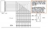
One thing to point out, the LEDs on the end (0 & 9) stay on twice as long as the other LEDs. If you want all of the LEDs to be on for the same amount of time, add an 11th LED (LED10) and connect output pairs (1,9), (2,8 ), (3,7) etc. together. In this case, output 5 drives the same LED in both directions, saving a diode/OR gate. The diodes on outputs "0" and "5" aren't logically needed, but are left in for matching LED light levels. You could also use four 2-input OR gates (74HC32) in place of the diodes.

A few more notes: The CD4017 outputs don't have much drive capability, you may want to use the 74HC4017 instead (Be aware the 'HC parts have a maximum Vcc of 6 Volts). Either way, it would help to use high-efficiency LED's (2mA drive). The JK flip-flop should be a negative-edge triggered version, like the 74HC112. If using a positive-edge version like the CD4027 or 74HC109, Cout from the 4017 needs to be inverted. Remember to tie reset pins to their inactive states, and clock enable pins to their active state.

I haven't tried the circuit out, so it may have some problems. Good luck!

Edit: I just noticed the comments in the attached schematics show doubled output pair connections. The output pairs for driving 10 LEDs are (0,9), (1,8 ), (2,7), (3,6) and (4,5).
The output pairs for driving 11 LEDs are (1,9), (2,8 ), (3,7), and (4,6).
 

Attachments

  • 4017_UD_11_Led_sequence.gif
    4017_UD_11_Led_sequence.gif
    9.1 KB · Views: 2,425
  • 4017_UD_10_Led_sequence.gif
    4017_UD_10_Led_sequence.gif
    8.7 KB · Views: 2,644
well,
it looks like "niq_ro" has cracked it. Respect.

Although he has used a half at a time,
i think you could use the whole set of ten outputs.

Ive drawn up a skeleton diagram,
i hope its method is clear.

In this arrangement the bi-stable doesn't necessarily
need to be a flip flop, the instruction to change
state could come from different places.

I am still thinking about each end of the 'scan' and
wondering if triggering the bistable could be arranged
to avoid the extra time at each end of the 'scan'.

Maybe it wont notice ...

Regards, John :)
 

Attachments

  • KIT-lites.jpg
    KIT-lites.jpg
    35.4 KB · Views: 2,417
Error,

excuse me, ive drawn the bistable incorrectly.
i did not mean to show it as two bistables.
rather than edit out my error, i am posting a correction.

Sorry about that.

John :oops:
 

Attachments

  • KIT-lites_733.jpg
    KIT-lites_733.jpg
    35.6 KB · Views: 2,161
Edited version of my previous submission. I have had second thoughts.
The circuit submitted by Laroche73 will not work properly. It will flash each LED twice per cycle. For example, LED 0 will light at states 0 and 9.

The circuit submitted by john1 won't work either. But it could be made to work with some changes. But you would need to use transistors as drivers since the current source capability of the 4017 may not be adequate.

A simpler solution would be to use a 10 pole change over switch or its electronic equivalent.

However, triggering the bistable is not a problem.

If the Bistable is a negative edge trigger, connect its Ck to output 9 of the 4017.

If it is a positive edge trigger, connect its Ck to output 0 of the 4017.

Len
 
bleh, i think ive figured it out...sorta, gona end up usin two 4017's, then have a flip flop on the last led, so that the pulses from the 555 go to the other 4017 chip which is wired to the same led's in reverse order...this circuit board is gona b a pain to lay-out...do i need diodes to avoid power going back to the other 4017?, or can the 4017 chip handle power going bak to its output......hope i didn't confuse u wit that...i jus don't want 20 diodes...seems like alot for a project that *should* b easier...im in gr12 in a highschool elt class doin this, haha, *should* b a peice of cake, o well...
 
4017 connections revisited

ljcox, take another look at the partial schematics I posted. The key to the circuits' operation is the extra "state bit" provided by the JK flip-flop, and when it's clocked. Although the output pairs from the 4017 are wired-OR, the return path alternates between the JK flip-flops' Q and Q/ outputs. The flip-flop is clocked using "C_out" from the 4017, so the state bit changes on the rising edge of output "5" (Sometimes a picture is worth a 1000 words, so I've attached a timing diagram). You're right though, "C_out" doesn't need to be used as the clock source. For a rising-edge triggered flip-flop, using output "5" as the clock source will accomplish the same thing (also, for a negative-edge triggered flip-flop, using output "4" as the clock source would work identically to using "C_out", the only difference is the duty cycle). The flip-flop could also be a D-type, as long as both "Q" and "Q/" outputs are available ("Q/" would be wired back to the "D" input to make a toggle flip-flop).

Initially, the "Q" return path is active (low) for counts 0-1-2-3-4, then the "Q/" return path is active for counts 5-6-7-8-9-0-1-2-3-4, then the "Q" path is active for the following 10 counts and so on (It helps to think of the circuit as a state machine having 20 distinct states).

This means the LED sequence for the 10 LED version is 0-1-2-3-4-5-6-7-8-9-9-8-7-6-5-4-3-2-1-0-0-1-2...

the LED sequence for the 11 LED version (equal ON time for all LEDs) is 0-1-2-3-4-5-6-7-8-9-10-9-8-7-6-5-4-3-2-1-0-1-2-3...

The circuit submitted by Laroche73 will not work properly. It will flash each LED twice per cycle. For example, LED 0 will light at states 0 and 9.

With the 10 LED version, it's true that LED 0 will light at 4017 states 0 and 9, but only when the flip-flop "state" bit has the correct polarity. The "knight-rider" effect is achieved. During the first 0-9 count sequence, output "0" lights LED 0 because "Q" is low, then output "9" lights LED 9 because "Q/" is low. For the second 0-9 count sequence, output "0" lights LED 9 since "Q/" is still low, and output "9" lights LED 0 since "Q" is low at that time. As mentioned in the earlier post, LEDs 0 & 9 stay on twice as long as LEDs 1 - 8.

For the alternate setup with 11 LEDs, each LED is on for the same amount of time, and output "5" only needs to drive one LED. Output "0" drives LEDs 0 & 10.

twisted_iggy - it looks like the design can be done with the parts list you were given, plus some steering diodes or OR gates, which are needed to prevent output contention. You're right, it does seem a bit complicated for a high-school electronics class. I'd ask to see your teachers' solution first :wink: .
 

Attachments

  • 4017_JK_waveforms.gif
    4017_JK_waveforms.gif
    7.4 KB · Views: 1,832
4017 connections revisited

My apologies, laroche73, I had missed the point about the FF clocking at 5. However, it does not meet one of the teacher's criteria. ie. that the count sequence be 0,1 ,2 ... 9, 8, 7 ...1, 0, ...

Incidentally, I don't know what the "knight rider" effect is.

I have attached an alternative that I believe meets the teacher's criteria.

Len
 

Attachments

  • LED_sequencer.gif
    LED_sequencer.gif
    7.4 KB · Views: 2,043
Knight rider

Hi, ljcox. The "Knight Rider" effect, as it's sometimes called, is just the back and forth pattern on the LEDs, and refers to a cheezy '80s TV show.

http://www.geocities.com/lemagicien_2000/elecpage/bounlite/bounlight.html & http://www.knightrideronline.com/krfaq.php#3-4

You are correct, LEDs 0 & 9 stay on for an extra cycle in the 10 LED circuit, that's why I included the 11 LED circuit. Technically, the circuit doesn't meet the class requirement, but it does show the back and forth effect can be done for 10 or 11 LEDs using a single 4017 and one flip-flop.

Edit: After giving it a little more thought, it's pretty easy to modify the 11 LED circuit to use 10 LEDs and have the desired sequence. All that's needed is to make the state machine have 18 states instead of 20. Tying output "9" back to the 4017's reset pin does this. A revised timing diagram is attached. Output "0" drives LEDs 0 and 9, and the output pin pairing is (1,8 ), (2,7), (3,6) and (4,5). The first nine states drive LEDs 0 - 8 in the forward direction, the next nine states drive LEDs 9 - 1 in the reverse direction, and so on. The same idea works for fewer LEDs as well. To drive 8 LEDs the state machine should have 14 states, so output "7" would be tied back to the reset pin.

Incidentally, the circuit you posted looks fine logically, but may have some trouble driving the LEDs. The 4017 has a low output drive capacity, and the current-limiting resistors between output pairs act as voltage dividers (ex, when IC2 output "1" is high and IC1 output "8" is low). As in all the circuits posted so far, the 4017 outputs need to be "ORed" together somehow, and it can be done through resistors, diodes or logic gates (OR gates, 2:1Mux, bus exchange switches). Using a logic gate has the least effect on LED brightness. Diodes add a small (~0.7V) voltage drop which can matter if using a 5V supply. Using resistors to do the ORing steals current from CMOS outputs that don't have much drive capacity to begin with, probably isn't the best approach.

As ljcox pointed out, using output "5" instead of "C_out" to clock the JK flip-flop allows a CD4027 to be used. That way the entire circuit can use CD4K parts and run off a 9 -12 V supply ('HC logic has better drive capability, but limits you to a 6 V supply).
 

Attachments

  • 10_LED_4017_JK_waveforms.gif
    10_LED_4017_JK_waveforms.gif
    7.8 KB · Views: 1,744
Status
Not open for further replies.

Latest threads

New Articles From Microcontroller Tips

Back
Top