Continue to Site

Welcome to our site!

Electro Tech is an online community (with over 170,000 members) who enjoy talking about and building electronic circuits, projects and gadgets. To participate you need to register. Registration is free. Click here to register now.

  • Welcome to our site! Electro Tech is an online community (with over 170,000 members) who enjoy talking about and building electronic circuits, projects and gadgets. To participate you need to register. Registration is free. Click here to register now.

Need help with a dead remote

Status
Not open for further replies.

CMServiceguy

New Member
Hi all. New here and looking for help repairing a remote control.

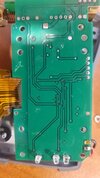
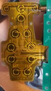
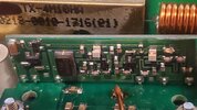
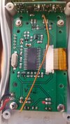
It is for a product called Yacht Controller. It's basically a system people use to wirelessly dock their boat. The remote just stopped working, will not power on. these units are waterproof for a little while but I'm positive this unit did not get wet.

I know nothing about circuitry repairs (ask me to install a radar, autopilot or satellite TV system and I've got you covered). There isn't anything more I can offer about the remote since I can't power it on and test the other functions. It was working fine before it just stopped but that is all I know.

Not looking for a free repair. Your time is valuable and I understand things cost money. I'm looking for help as I gave my customer my stock/test remote and would like to repair this for a replacement.

Thank you,
Rich
 
Welcome.
Dismantle carefully on a clean table, rub battery contacts, make sure those battery contact springs are well soldered to the printed board, clean the board and the buttons with a pencil eraser. Hard to check, but happens the board can have an invisible crack much thinner than a hair. Inspect with a loupe. If infrared, aim to a camera as on a phone to confirm emission.
 
Thanks for responding. As far as I can tell with my meter, the connections/voltage are all good through the first diodes/resistors. Past that, I'm lost. I'll recheck as a digital meter can give a false positive (as we all know) and I didn't think about a cracked board.

Thank you,
Rich
 
If the remote control is found healthy, go for the other half : the receiver, its antenna, supply, wiring, interface to actuators... Is there even a LED that shows a signal is being received from the remote ? If not, I would implement such. Edit : Oooops, reading again; your remote makes it work...
Well, look for cracks gently flexing the board if there is a chance someone sat on it.
You can compare resistance values the good against the bad...
 
Thank you all. Here are the photos. I included a close up of the IC because they intentionally scratched off the identifying marks. If anybody can ID it great.

The remote is dual freq. RF (966/433 Mhz IIRC). It can be paired with any receiver and while I have one, I need the remote to actually turn on in order to pair it.
 

Attachments

  • 20230321_173154.jpg
    20230321_173154.jpg
    1.4 MB · Views: 132
  • 20230321_173204.jpg
    20230321_173204.jpg
    1.4 MB · Views: 147
  • 20230321_171936.jpg
    20230321_171936.jpg
    893.6 KB · Views: 131
  • 20230321_171910.jpg
    20230321_171910.jpg
    1.5 MB · Views: 142
  • 20230321_172135.jpg
    20230321_172135.jpg
    1.3 MB · Views: 140
Thank you but I have no way to integrate this. I am not skilled in electronics repair/design. I am skilled in electronics installations/diagnostics for marine systems.

This is all Greek to me and you guys/gals are all magicians as far as I'm concerned.
 
Can you get a clearer picture of the possibly damaged part?
Are you able to identify power pins on the chip?
If there are any electrolytics on the board then they may identify the ground line enabling you to identify ground connections.

Mike.
 
Electrowhatsis? How many Egyptians do you want?

Seriously, I have no idea what one is from another. Like I said, I am an idiot with this part. While I can install and diagnose issues with radars and such, the intricacies are beyond my scope. However, if you tell me what to look for, I am certain i can help.

I'll try to get a better pic of the damaged part but the thing is less than a sixteenth of an inch across so it's basically invisible.
 
In the fourth picture in post #7 you can see the (black) ground wire in the bottom left corner. The PCB has a ground plane (large area of copper) comming from that connection. Above tthe connection and to the left of the IC is what looks like a crystal (the shiney metal can) The connections on the top and bottom appear to connect to the two (tiny) capacitors next to it and then to pins 9 & 10 of the IC (numbers are anticlockwise starting at the dimple in the top left). The outside connections of the capacitor should be connected to groung which suggests pin 8 is also ground.

Green are the crystal connections, black is ground,
board.jpg


Can you confirm any of this?

Also, when the number has been removed from an IC it can sometimes be made visible by applying a wet finger to it. does this work?

Mike.
 
The IC appears to be a 28 pin PIC; the oscillator and ground pin etc. match, as well as the power and ground pins on the opposite side that stand out from the other connections.

The damaged component at the upper right appears to just be a decoupling cap. The larger cap at the top left of that sub board also looks damaged. The unit possibly got dropped??

This looks like a possible failure cause to me - the left hand side of that cap may be cracked off the PCB??

Boat_Remote_2.jpg


I'd suggest also checking the solder joints on all the pins that mount that sub-board to the main board - both the upper side as visible in the photo, and on the underside of the main PCB.
 
The IC does look like an old 28 pin pic chip I.E.
pic.png


Are you able to confirm that pins 8 and 19 are connected together. If you can't don't worry, it's just a curiosity kind of thing.

The 5 pin connestor left and just above the IC could be an In Circuit Programming connector but the pinout is not one I'm familiar with (pin 2 if Vpp - not pin 1 as usual).

Don't know why they would remove the number as they contain a (protected I assume) program which would be impossible to copy.
I'd go with RJ's suggestion.

Mike.
Edit, the number shown in the picture is just one of many it could be.
Edit2, do you know an approx year of manufacture?
 
The IC does look like an old 28 pin pic chip I.E.

It could well be, you find PIC's in almost everything. Or it could be any other 28 pin microcontroller, but PIC's tend to be one of the most popular options.

But why rub the markings off?, knowing it's a PIC (or whatever it is) is of no use to you, as you can't buy a ready programmed chip for it.
 
Ok.... lot going on here.

Pommie: You are correct in everything you say. Everything is connected and tested back from ground wire through to the IC.

The chip has been thoroughly scraped clean. I believe the idea behind it is to prevent someone from copying the design precisely. This company has had this in the USA as the only option for a long time. Only now are other competitors coming into the market as, I guess, the patents are expiring. That would be the only reason I can see for removing the markings.

Pins 8 and 19 are both grounded. That 5 pin connector would be for initial programming? I've seen this type on other devices and the pins were 3.3v/Rx/Tx/Gr/GPIO14. when I put a 6v test light from positive to terminals 2,3,5 (respectively from top to bottom), I get the power and transmit LEDs to turn on. Terminal 1 goes to ground. Pin 4 goes to pin 1 (MCLR/VPP) on the IC.

The unit, according to the serial number, was SOLD in 2016. Manufacture for these is pretty consistent year for year so I would feel safe saying the unit was manufactured within a two year range prior to 2016.


rjenkinsgb: These being on boats, anything is possible when it comes to dropping or getting knocked around. This customer is usually very careful with his belongings but that doesn't mean it couldn't have happened.

As for checking solder joints, I don't have a microscope. I used the zoom on my phone to get the pics. Even with a magnifying glass it's difficult to see.


I think that's everyone/thing answered. I'll see what I can do with the solder joins.

Thank you all.
 
Ok.... lot going on here.

Pommie: You are correct in everything you say. Everything is connected and tested back from ground wire through to the IC.

The chip has been thoroughly scraped clean. I believe the idea behind it is to prevent someone from copying the design precisely. This company has had this in the USA as the only option for a long time. Only now are other competitors coming into the market as, I guess, the patents are expiring. That would be the only reason I can see for removing the markings.

It's just to be bloody minded - it's not preventing anything, it's a micro-controller, and it's completely useless without the content (which will be protected, so you can't read it). If you buy a computer game on a CD-ROM, do they remove all the markings so you won't realise it's a CD-ROM? - no, of course not, it's exactly the same as here.

It's almost certainly not patented, as there seems nothing that could be patented? - and in the unlikely event it was patented, then the patent would probably show what the chips were :D

If anything is patented, it would have to some small part of it, something unique which you could get a patent for, but for a simple RF remote it's all pretty basic stuff - and rubbing the numbers of the chips is just a measure to stop other people trying to repair it.

Pins 8 and 19 are both grounded. That 5 pin connector would be for initial programming? I've seen this type on other devices and the pins were 3.3v/Rx/Tx/Gr/GPIO14. when I put a 6v test light from positive to terminals 2,3,5 (respectively from top to bottom), I get the power and transmit LEDs to turn on. Terminal 1 goes to ground. Pin 4 goes to pin 1 (MCLR/VPP) on the IC.

I'm quite horrified at you randomly sticking a test lamp on it - you could easy kill something doing that - test lamps (where applicable) are for testing crude electrical things, not electronic ones. If you want to test things, use a multimeter.

It still looks VERY like a PIC, with Vpp/MCLR on pin 1, the clock oscillator on pins 9&10, Vss on pin 8, and (probably) Vss on pin 19 with Vdd on pin 20 (19 and 20 are missed out from the ribbon cable).

The programming pins on such a PIC are ICSPDAT on 28, ICSPCLK on 27, Vpp on 1, Vss (gnd) on pins 8 &19, and Vdd on pin 20
 
Ask someone to desolder the broken component. (left post #8) as may be shortcircuited when got smashed.
Show that skilled person the equal one on the working remote; try to have it identified and measured. Obtain one desoldering from any junk appliance and have it soldered to the failed remote.
 
Status
Not open for further replies.

Latest threads

New Articles From Microcontroller Tips

Back
Top