Here is a thread where Eric helped me get a pot going. https://www.electro-tech-online.com/threads/ltspice-potentiometer.117290/?highlight=potentiometer
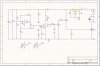
You can take out all the step parm. and just use 2 resistors (Say 2 5Ks). The only other problems I see is the base of Q2 is not hooked to the pull up resistor and the inductor (Motor) needs a couple of ohms of series resistance.
You can take out all the step parm. and just use 2 resistors (Say 2 5Ks). The only other problems I see is the base of Q2 is not hooked to the pull up resistor and the inductor (Motor) needs a couple of ohms of series resistance.
Last edited:
 , I took your advice and it was really helpful