Continue to Site

Welcome to our site!

Electro Tech is an online community (with over 170,000 members) who enjoy talking about and building electronic circuits, projects and gadgets. To participate you need to register. Registration is free. Click here to register now.

  • Welcome to our site! Electro Tech is an online community (with over 170,000 members) who enjoy talking about and building electronic circuits, projects and gadgets. To participate you need to register. Registration is free. Click here to register now.

Need Help recreating circuit with 25 year old schematic

Status
Not open for further replies.
Hey guys,

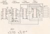
I am new to this board and to electronics in general. When I was a little kid back in the 80s, my uncle built me a little box that, on the outside, had only an 8 segment LED array, a rheostat and an on/off switch. The box simply controlled the LED array and the circuitry made the LEDS go back and forth, The rheostat would control the speed of the back and forth motion.

Long story short, my uncle passed and in cleaning out his stuff, I found the schematic he drew to build the box for me. I no longer have mine but I want to build another one, and I want to build it exactly the way my uncle did, using the same components. I'm sure things have improved in 25 years but I want this just the way he built it.

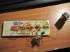
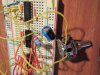
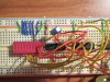
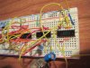
I have all the required components (ICs, pot, capacitors and resistors, etc) mounted on a solderless breadboard, but I can't for the life of me get it to work. I attach a 9v battery and only the first LED lights up, even if the potentiometer is disconnected!

If you guys could guide me through this, it would mean a lot to me. I've attached a pic of the schematic (cleaned up a bit as some was hard to read) along with some pics of my breadboard.

Thanks,
Kyle
 

Attachments

  • img334.jpg
    img334.jpg
    1 MB · Views: 245
  • th_IMG_1582.jpg
    th_IMG_1582.jpg
    375.7 KB · Views: 195
  • th_IMG_1583.jpg
    th_IMG_1583.jpg
    325.2 KB · Views: 186
  • th_IMG_1584.jpg
    th_IMG_1584.jpg
    292.1 KB · Views: 181
  • th_IMG_1585.jpg
    th_IMG_1585.jpg
    335.3 KB · Views: 169
Last edited:
Double check for wiring errors. All it takes is one misswire for it not to work. That's the most common cause of a breadboard circuit not working.

Edit: One way to check wiring is with an ohmmeter while marking off the measured connections on the schematic with a highlighter.
 
Last edited:
Hello,

I was going to ask what kind of test equipment do you have? A meter?

The way to trouble shoot this circuit is to start with the oscillator and make sure it is pulsing, then make sure the decade counter outputs are pulsing, then make sure the decoder outputs are pulsing. In other words, stage by stage starting with the first and progressing to the last.
If the pulse period of the oscillator is long you should see the meter reading jumping up and down. If it is short, you'll see some value that is about midway between the positive voltage rail and ground.

I dont see any bypass caps either. You may need those if you get erratic counts once you get it working.
 
Last edited:
I have a multi-meter and will try the suggestions above. Can someone compare the potentiometer on the breadboard with the schematic and see if i set it up properly?
Thanks,
Kyle
 
For starters 1 side of your rheostat is not connected to any thing, have another look at the schematic all 3 legs are shown as connected.

Otherwise your wiring is too much of a mess for me to follow and my eyes became knotted attempting it.

Pete.
 
Pot looks OK, at least so far as one can tell from the photos.

I'm wondering about some of the unconnected pins of the chips. If any of these are inputs, they would be "floating" and could cause problems. All unused inputs should be tied either to ground or to V+.
 
For starters 1 side of your rheostat is not connected to any thing, have another look at the schematic all 3 legs are shown as connected.

Doesn't make any difference. A pot connected as a rheostat with 2 connections works just the same. Think about it.

(Some folks like to tie the unconnected end to the wiper for safety purposes, but that's way overkill here.)
 
I've studied the data sheets for the chips and some of those connections are marked "NC" (not connected) but I think a couple had a purpose...so those may need grounded...

Kyle
 
If the unconnected pins are NC, don't sweat it.
If they're inputs that are active high, tie them to ground. Active low, tie them to V+.
If outputs, don't worry about them.
 
First i would do is to increase the Capacitator C1.
That will slower the Oscillator and give you the possibility to measure with your Multimeter.
Then check the pulses on PIN4 of 4049. Are they present ?
If this works the 4510 should count.

When this is working you can check the 4028 decimal decoder.
The acording output of binary bit pattern of the 4510 should be active.
When this all is working Led line should light up minimal once.

The last in this Chain is the 4013 that shoud create the UP/Down Signal for the 4510 when end of LED ladder is achieved.

If one thing in this Chain wouldn't work ckeck Power an Reset signals of that.

In C-Mos technology no input! can be leaved open - It always must conected with a fixed Signal ( GND or VCC ).
If you don't do that is is possible, the Chip is oscillating on an high frequency.
 
well, i connected the needed pins and swapped out the pot for another one, and we are getting closer! the LEDs will now light in order, but instead of sweeping back when it reaches the end of the LED array, it simply starts over at the beginning. Getting closer! Ideas?

Kyle
 
and also, theres only a "sweet spot" in the middle of the pot's range where it works...too far turned left or too far turned right and the LED it was on just stays lit...but in that small range I can adjust the speed...

Joe
 
I do remember that the LED swept back and forth, not just one direction....what would i need to do to make that happen? And what causes the potentiometer issue mentioned previously?

Thanks guys! I'm closer than I was a few hours ago.
Kyle
 
Pin 10 on the 4510 controls the direction of the direction of the counter. Perhaps that also controls the direction of the sweep. Is that signal (Pin 10) changing?
 
Status
Not open for further replies.

New Articles From Microcontroller Tips

Back
Top