Continue to Site

Welcome to our site!

Electro Tech is an online community (with over 170,000 members) who enjoy talking about and building electronic circuits, projects and gadgets. To participate you need to register. Registration is free. Click here to register now.

  • Welcome to our site! Electro Tech is an online community (with over 170,000 members) who enjoy talking about and building electronic circuits, projects and gadgets. To participate you need to register. Registration is free. Click here to register now.

need help making a circuit to sense PWM on 12v auto headlight (DRL)

Status
Not open for further replies.

Paiko

New Member
ok... what the problem is that the daytime running lights (DRL) on the new cars are using PWM for dimming the headlights during the day (full 12v at night)... i do not know the frequency and i think the voltage drops down to about 10v (under load - do not know unloaded)

i need the full voltage to run the ballist for the HID lighting...

i have used the signal to gate a SCR and run a relay that supplied the HID's

what i want to do on my truck is use that DRL signal to turn on a relay that turns on the fog lights and when the DRL signal goes away (full 12v) the same relay drops out and i can light up the HID's

not sure how to do this.... any ideas???
 
I would drag my o'scope out to the car to see what the waveforms look like. If you don't have a scope, do you have a DigitalMultimeter to make some basic measurements?

If so, try reading the voltage on the wire going to your DRLs. First try reading the day/night DC Volts. Then also read the day/night AC Volts.

I'm trying to determine if the PWM goes away totally (so the signal is pure DC only; no AC) at night. If so, then detecting the absence of PWM should be easy. If on the other hand, the PWM stays, but becomes like 98% on, vs 50% on during the day, detecting that is a little harder...
 
OK.. i'll do that tomorrow duing the day...

no scope but i'll be able to get freq and voltages

i have a fluke 87 i think i can get an idea of the wave with that... hmmm

thanks for the help.... Aloha, Stan
 
got some voltages... no scope avalible...

14.4v dc headlights on (0v ac - 0 Hz)

12.1v dc DRL on (5.1v ac - 128 Hz)

thanks for the help... Aloha, Stan
 
How about using a 555 as a retrig monostable missing pulse detector. While the PWM is present, the output of the 555 is high. When the PWM is gone (input steady high), then the 555 output is low.
 

Attachments

  • PwmDetector.jpg
    PwmDetector.jpg
    209.6 KB · Views: 3,376
Last edited:
thanks for the circuit... it has been a very long time since i made any kind of 555 circuit... (20 yrs ago in electronics school)

I'll try to build this and use it to run a Bosch type automotive relay...

thanks again for all your time.. it is greatly appreciated !!!

Aloha, Stan
 
hey mike, thanks for the circuit... just finished making it and tested it on the truck... so far so good.... now i have to setup the relays to cutout the pulsing voltage to the HID's and hook up the HID's

thanks again for your time and help on this!!!!!
 
They got software scopes for your laptop. I use Virtins which is perfectly suited to the frequencies you are using. It used the microphone input on the laptop for the probe. They have some free ones, but usually don't have allot of features like storage capability.

I think this ones free:

**broken link removed**
 
They got software scopes for your laptop. I use Virtins which is perfectly suited to the frequencies you are using. It uses the microphone input on the laptop for the probe. They have some free ones, but usually don't have allot of features like storage capability.

I think this one is free:

**broken link removed**
 
Storage capability? Every version of windows linux or MaxOS I've ever used comes with a sound recording application =)

You can feed .wav files directly into Linear's LTSpice simulation software as a voltage source scaled any way you want and do FFT or even feed it into simulated circuits and watch the output. It however is not real time.
 
Last edited:
I have noticed that Chrysler (and their Jeep) does not dim their high beam daytime running lights.
When it is dawn, dusk or cloudy they blind all oncoming drivers.

They should not use high beams and they should dim them.
 
Storage capability? Every version of windows linux or MaxOS I've ever used comes with a sound recording application =)

You can feed .wav files directly into Linear's LTSpice simulation software as a voltage source scaled any way you want and do FFT or even feed it into simulated circuits and watch the output. It however is not real time.

Well he may not have spice. I was just letting him know you can get them free on the internet. I don't think I like the one I just posted. I tried it out. I had a really neat one that was free and it had a spectrum analyzer too but I can't find it.
 
LTspice is free =)
 
I see this is and old thread, but with multiple Google searches this come the closes to what I'm trying to do. I'm new to electronics so please excuse any gaffes.
Here's is the setup. The dome light in the car comes on slowly when you open the door. It is controlled by the cars PWM circuit.
The + side is at a constant 12v the - side is pulsed. This is the only place I can find that signals that any of the doors are open.
I've built an ambient lighting LED RGB system. What I need is a circuit will detect any current flow in the dome light circuit and activate a relay.
The reason for the relay is, along with another relay and some resistors it will tell the PIC the condition of the car.
Run/accessory off Doors open <--- Wake to White light fade when door closed to ambient setting
Run/accessory on Doors open <--- White light fade when door closed to ambient setting
Run/accessory on Doors close <--- Run Ambient lighting color selector
Run/accessory off Doors closed <--- Fade to lights out sleep mode.

Thanks in advance..
 
Why dont you just mount a small LDR inside the dome light, such that when the lamp is illuminated, the low resistance of the LDR is detected by your PIC? No relays needed. Totally isolated from the car's circuitry.
 
Last edited:
I mulled that one over. That would work great if I didn't need to tell the controller if the car was in ACC/Run also. How about this for the off the cars PWM.
**broken link removed**
I just don't know how to make that circuit full on with any input from the cars PWM
 
Last edited:
You might need to filter the PWM so that the relay doesn't try to follow it.

If you powered the LDR from the key-switched 12V, and followed it with a voltage divider to constrain the voltage swing at the PIC to >5V, it would be equivalent to the relay...
 
Thanks, I'll give those a try.

Edit:
MikeMI with a little testing your LDR idea seems like the way to go.
Thanks for nudge in a new direction..... Never would have thought of it.
 
Last edited:
How about using a 555 as a retrig monostable missing pulse detector. While the PWM is present, the output of the 555 is high. When the PWM is gone (input steady high), then the 555 output is low.

Back to the OP's topic. I am an extreme novice.


Pin 1: self explanatory

Pin 2: is receiving signal from V2 ( the bcm outputting a pulse width signal or a constant 14v signal). It is also receiving current from Pin 7 AND from Vdd, via R1. I am not sure what the signal from Vdd is doing.

Pin 3: This is the output that outputs 12v? when Pin 2 goes "low" (less than 1/3 Vdd?), otherwise it outputs nothing? when Pin 2 goes "high"

Pin 4: tied to Vdd to prevent accidental reset...

Pin 5: Left open. Why is this not tied to ground via a capacitor?

Pin 6: Threshold: Receives signal from what appears to be Pin 7 and Vdd via R1. Again, not sure what's going on here.

Pin 7: Outputting signal to Pin 6 and to Pin 2. I understand this pin also works as an auxiliary output. When Pin 2 goes High, Pin 7 goes low?

Pin 8: Takes in Vdd.

Question:

What is the other side of of C3 and C2 hooked to? Ground?


So how does the OP use this then to trigger Light A when the PWM signal is on, and trigger Light B instead when the PWM signal disappears? Im sure the answer is right in front of my nose but I just can't seem to totally understand the process.

Help?
 
Back to the OP's topic. I am an extreme novice.

Pin 1: self explanatory

Pin 2: is receiving signal from V2 ( the bcm outputting a pulse width signal or a constant 14v signal). It is also receiving current from Pin 7 AND from Vdd, via R1. I am not sure what the signal from Vdd is doing.
When the TRIG input is pulled below 1/3 of Vcc (4V), the 555 is "triggered", meaning its OUT pin goes high (near 12V), and the DISCHarge transistor (pin 7) is turned on, discharging C3 to near ground. This happens as long as the PWM input is low...

Pin 3: This is the output that outputs 12v? when Pin 2 goes "low" (less than 1/3 Vdd?), otherwise it outputs nothing? when Pin 2 goes "high"
It outputs either almost 12V (high) or almost ground (0V, low). It can source or sink about 200mA

Pin 4: tied to Vdd to prevent accidental reset...
To disable the RESET pin, i.e to prevent it from doing anything...

Pin 5: Left open. Why is this not tied to ground via a capacitor?
You can if you want to. The simulator doesn't care. A real 555 might.

Pin 6: Threshold: Receives signal from what appears to be Pin 7 and Vdd via R1. Again, not sure what's going on here.
When the PWM signal goes high, the RESET condition goes away, turning off the DISCH transistor. Now Diode D1 is reversed biased (blocking), so the timing capacitor C3 begins charging through R1. If another PWM pulse comes along before the voltage at Pin 6 THRS reaches 2/3 of Vcc (8v), then the 555 is triggered again (re-triggered?). If PWM stops high, then the 555 times out, Pin 3 OUT goes low, the lack of PWM is detected, job is done...

Pin 7: Outputting signal to Pin 6 and to Pin 2. I understand this pin also works as an auxiliary output. When Pin 2 goes High, Pin 7 goes low?
See above.

Pin 8: Takes in Vdd.
Question:

What is the other side of of C3 and C2 hooked to? Ground?
All the upside-down Δ symbols are ground, and are all implicitly connected together. Just short-hand in lieu of connecting them all with expicit wires in the schematic.

So how does the OP use this then to trigger Light A when the PWM signal is on, and trigger Light B instead when the PWM signal disappears? Im sure the answer is right in front of my nose but I just can't seem to totally understand the process.

Help?
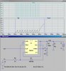
The 555 OUT pin3 is capable of sourcing or sinking about ~200mA. It can drive a small 12V relay directly (with a snubber diode across the coil), or by adding a NFET or PFET transistor used as a power switch, could switch 10s of A. Here is a similar circuit that shows the 555 driving a relay.
 
Last edited:
Status
Not open for further replies.

Latest threads

New Articles From Microcontroller Tips

Back
Top