Continue to Site

Welcome to our site!

Electro Tech is an online community (with over 170,000 members) who enjoy talking about and building electronic circuits, projects and gadgets. To participate you need to register. Registration is free. Click here to register now.

  • Welcome to our site! Electro Tech is an online community (with over 170,000 members) who enjoy talking about and building electronic circuits, projects and gadgets. To participate you need to register. Registration is free. Click here to register now.

Need help in explaining a circuit.

Status
Not open for further replies.

zee3b

New Member
Hey guys.
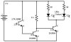
I need help in explaining the circuit in attachment. Its a dark detector the LED's attached light up when its dark. Can someone explain the whole circuit in detail to me explaining what each and every part does in this circuit.
Thanks a lot.
 

Attachments

  • untitled.JPG
    untitled.JPG
    15.4 KB · Views: 164
Last edited:
When it's dark, the LTR-3280E light sensor is off and conducts no current thus the middle 2N3904 transistor is also off. The current through the 5k resistor therefore flows into the base of the right transistor, which turns it fully on (like a switch) and allows current to flow through the two LEDS so they emit light. The 50Ω resistors limits the LED currents to the proper level.

When it's light, the light sensor is on which conducts current from the 3V battery supply into the base of the middle 2N3904 and switches it on. This transistor then conducts all the current from the 5KΩ resistor to ground. There is thus no current going to the base of the right transistor and it is off. Consequently, no current flows through the LEDs, which are also off.

Clear enough?
 
Status
Not open for further replies.

Latest threads

New Articles From Microcontroller Tips

Back
Top