Continue to Site

Welcome to our site!

Electro Tech is an online community (with over 170,000 members) who enjoy talking about and building electronic circuits, projects and gadgets. To participate you need to register. Registration is free. Click here to register now.

  • Welcome to our site! Electro Tech is an online community (with over 170,000 members) who enjoy talking about and building electronic circuits, projects and gadgets. To participate you need to register. Registration is free. Click here to register now.

Need help for my min project

Status
Not open for further replies.

shawnsoc

New Member
Need help in design of a LED dimmer

Hi Everyone, I'm new in circuit design.
Need someone to help me out with my led dimmer wiring project.

I have a LED 7V 700mA, Power source 12V 1A, Cooling fan 12V 0.02mA
and a on off switch.

So what i need is someone teach or guide me how to design a board for this.

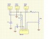
Power on and light up my LED, But i want to have a dimmer to control total off and max out put to my LED.

Overall a LED dimmer Circuit.

Thank in advance to everyone here
 
Last edited:
You'll need a lot more than what you have. The simplest/most efficient way would be to use a 555 for PWM'ing a drive transistor. There are hundreds of circuits available using Google that will show you what you need if you look for them, or search the forums yourself.
 
Hi Sceadwian, thank alot for your reply.

But first i really need some help on the startup of the design.
 
Yes shawnsoc, I'm aware of that which is why I said you should be searching on Google right now for the hundreds if not thousands of circuits that do EXACTLY what you want instead of posting on this forum right now. No one will help you with problems that the solution is blatantly available elsewhere if you'd put forth even the slightest bit of effort.

Come back with questions about a possible design that you've come across and people might talk to you then. We will not do the work for you, we will guide to the proper solution, or you will learn nothing.
 
Thank you

Hi Sceadwian,

Thank for your speedy reply.
Got it thank i have attach a drawing and need advice of how to change the Resistor and Capacitor i will use a Variable Resistor to control the voltage/current to the LED.
 

Attachments

  • 5v.JPG
    5v.JPG
    61.8 KB · Views: 213
I think you may want this circuit, **broken link removed**

also if you are just starting id suggest using a breadboard to test things on before doing a pcb,

and also do you want the fan to dim too? or just the LED??

PIN 3 is your output on the 555 timer IC, C1 R1 & R2, use about 10-100uF capacitor(stay under max rating) , R1&R2 about 1M - 10k. use trial and error....
 
Per Sceadwian all you want is a simple PWM circuit and one built around the 555 timer chip would work fine. Give this link a read and then give this link a read. Both of those links will give you a few variations of 555 circuits that should work. I have no idea what the schematic in your image is?

Ron
 
I think you may want this circuit, **broken link removed**

also if you are just starting id suggest using a breadboard to test things on before doing a pcb,

and also do you want the fan to dim too? or just the LED??

PIN 3 is your output on the 555 timer IC, C1 R1 & R2, use about 10-100uF capacitor(stay under max rating) , R1&R2 about 1M - 10k. use trial and error....

Doggy, that is a 555 timer configured as an astable multi-vibrator which I do not believe would be suitable for PWM applications like dimming or motor speed control. I agree with the breadboard, just don't think the linked circuit is what is needed (wanted). Additionally while pin 3 of a 555 is normallt used as Q (output) that is not always the case with 555 PWM circuits as can be seen here.


Ron
 
help me, please!

hello every body
could you help me!
i want to design a circuit to control DC motor,
the motor can run on few minutes and then it switch off on few minutes, after it run again, times can show on led 7 segment.
if you have a diagram, please send for me,
thank you verry much!
 
ducleboykuty,

It is not polite to HIJACK someone elses thread, and if you want answers to your question then start your own thread.

Tip......... dont just scream for help in your thread title, use a title that surgests what your question is about.

Next tip, is do some research yourself and come back with some circuit diagrams that we can help you with, we all dont just sit here waiting to draw you a schematic.

Pete.
 
Well correct if im wrong but i think what you need is something much simpler than using a 555 timer.
Wouldn't be enough to place the power source, then a variable resistor (at the most 5k), then your LED and finally back to the power source. All connected in series.
 
Kind of moicez, the problem would be heat. The resistor would have to be rated for 5 watts, and all that energy would be wasted. PWM'ing with 555 is more efficient and the costs of the components are likely going to be lower. 555's are NOT that complicated to use, there are so many example circuits on the web that all you need to do is search for a few minutes and purchase and assemble the components, if you want you can even buy kits.
 
okay so it's not the proper potentiometer, but still it's way simpler (less components) to implement then a 555 timer. What shawnsoc needs is to dim an LED, why not a 4-5 component circuit in series using a potentiometer to dim the LED?
 
It's wasteful and it's more expensive than a decent 555 based circuit.
 
expensive?? If you use a 555 timer, you need a lot more componets, resistors, capacitors, the 555 IC, diods, etc. A potentiometer is not expensive I get them for a buck (at the expensive store).

Here is a website that can help you'll see its not wasteful at all. How to Make an LED Dimmer | eHow.com
 
All the components required for a 555 dimmer should cost under a dollar, and the primary reason not to use a POT is that you're just burning the power. 5 watts is a modest amount of power to have to get rid of.
 
thank you for your information
if i use 555 , i must do delay time
the hight pulse will remain on 15 minutes. and low pulse will remain on 15 munites
this way can't , because register what i need have not enough value to delay output in 15 munites
 
Status
Not open for further replies.

Latest threads

New Articles From Microcontroller Tips

Back
Top