RayRay1132
Member
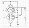
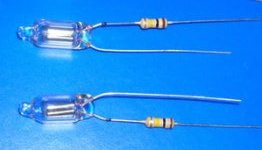
So I recently got my hands on a box of ne-2 neon bulbs and I wanted to make a 7 segment display with those bulbs but I need an opinion on how to interface an Arduino to them. I was thinking I could run the bulbs in parallel, (like in the picture below) and have a relay on each bulb. (Yes, I know I drew switches not relays on the schematic). It would probably be 2 bulbs per segment actually, but for simplicity sake I drew the schematic with 1. Is there a better way to do this than just connecting an Arduino to the relays?
Also I know I can just buy a 7 segment display, but where's the fun in that.
Thanks in advance -Ray
Also I know I can just buy a 7 segment display, but where's the fun in that.
Thanks in advance -Ray