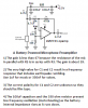
The LMV721 has a fairly high input bias current so its bias resistors R1 and R2 are 4.7k when the supply is only 3V. But with a 5.5V supply their values can be 10k each. My circuit uses 100k each.
The electret mic with the resistor that powers it has an output resistance of only 2.5k with a 9V supply and is about 2k with a 5.5V supply.
Then the ratio of the mic resistance to the preamp input resistance is only 2.5 times so the output level from the mic is reduced.
My circuit does not reduce the output level from the mic.
Here is a fairly good mic preamp using an LMV721 opamp: