Continue to Site

Welcome to our site!

Electro Tech is an online community (with over 170,000 members) who enjoy talking about and building electronic circuits, projects and gadgets. To participate you need to register. Registration is free. Click here to register now.

  • Welcome to our site! Electro Tech is an online community (with over 170,000 members) who enjoy talking about and building electronic circuits, projects and gadgets. To participate you need to register. Registration is free. Click here to register now.

Need chip to handle surges at input to power supply?

Status
Not open for further replies.

Flyback

Well-Known Member
Hi,
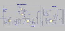
We are doing a Full Bridge, 10-36vin, 32vout, 300wout, 125kHz.
The input will see surges to MIL-STD-1275E and also DEF STAN 61-005 Part 6.

The LTC4364 is the beefiest of all offTheShelf surge protectors, but isn't capable of handling these standards' surges. Do you know of any that do, or are we looking at a home brew circuit only?

LTC4364
https://www.analog.com/media/en/technical-documentation/data-sheets/ltc4364-1-4364-2.pdf

MIL-STD-1275E
http://everyspec.com/MIL-STD/MIL-STD-1100-1299/MIL-STD-1275E_45886/

DEF STAN 61-005 Part 6
https://global.ihs.com/doc_detail.cfm?document_name=DEF STAN 61-5: PART 6&item_s_key=00517937
 
..thanks, unfortunately, the chips referred to in that can only be used with up to 4A output...that woudlnt be enough for us......

Thanks again...the two docs you very kindly present (from ti.com and analog.com) are the ones i also found...and they are the only chipsets for this standard...however, in our case, they are simply inadequate, as can be seen by reading those docs, they are not good for 300W.......As such, we are looking at a custom linear regulator design. And as such, i am wondering whether it would just be better to simply boost up the input voltage with a boost converter, to 100V...and then use that as our "normal" Vin to our full bridge SMPS...then when the surge happens...its just a "normal" voltage and nothing to worry about. ?....so all that would be needed is a bypass diode to bypass the boost inductor during the surge.

Do you agree, the "boost converter" solution is necessary (the simplest way) for the 300W case which we have?
 
Last edited:
...As you know, certain 28V automotive bus systems are saidd to suffer surges of "100V for 50ms". MIL STD 1275E tells that equipment connected to the 28V bus must keep delivering max load power throughout this surge. (ie, not just simply switch the surge out from its inputs)

Page 3 of this below, tells what causes the surge voltage of "100V for 50ms" on the 28V bus of certain automotive systems...
ti.com surge protector App Note:

..it says that these such surges "occur during motor events, such as the main turret turning, which is then seen by any accessory that is connected to the 28-V bus."

...Do you agree that this just doesnt sound right? Admittedly the current drawn from the 28V bus to turn the turret would be high. ..Then when the turret stopped turning, the energy in the stray inductance of the 28V bus would need somewhere to go....but surely it would simply go into the input capacitor bank of the turret motor, and thence not cause any overvoltage at all?....
...If the input capacitor bank gets dried out (eg with age, wear-out, etc), and becomes less in capacitance, then the stray L energy would still need somewhere to go, and so would surely charge up that input capacitor bank to more than 100V....in which case , any item on the 28V bus, that was in accordance with MIL STD 1275E, (ie, protected up to 100V surge) would fail anyway?
As such, would it not be better to simply switch out the surge, rather than try and port the device running current through an enormous, step-down, linear regulator, during the surge? Switching out the surge would result in non-service of the load for approx 100ms or so, but at least it could resume operation after that......i mean, you could always make the device go into "power throughput limited operation" mode during the surge aswell, so that if it happened to be on light load at the time of the surge, then the Vout woudlnt drop out at all anyway.
And in any case, many devices have an input battery which would see them through a 100ms surge anyway.
Isnt this standard ill thought out?

..Also, its wrong to call it a "voltage surge"...since it is a surge caused by current flow in the stray inductance..when the turret stops turning, the voltage on the bus will rise to whatever voltage it rises to, in order to keep the broken stray inductive current flowing.

Also, since the turret motor current is known, and so too is the stray inductance of the 28V Bus...then why not just put a proper surge arrestor on the 28V bus, to handle that?.....So, why put "ride through" surge protection in every single device? In any case, if all the devices on the 28V bus are on light load when the surge happens, then without a surge arrestor, the bus voltage will rise to well over 100V anyway.....making MIL STD 1275E a waste of time.
So surely you agree, that what is needed, is a proper surge protector on the 28V bus.....and nothing more than simple "switch-out" surge protection in every device on the bus?


Please do not fear giving away military secrets by responding to this, virutally the entire Western Power Electronics and SMPS sector has already been outsourced to outside of the West anyway.....leaving the West massively way behind in this respect, so you'll only be telling things that those outside the West already know far batter than the West anyway.
 
Last edited:
Just now found out that our 300W converter, (10-36vin), must also keep supplying 300W throughout the attached load dump surge aswell...
I believe you would agree that this needs us to boost up the input voltage to 175V, and beat the surge like that?.....

So i believe we need a triple cascaded boost converter...and three of those in pllel, at the front end...then we beat the surge!.....we dont even see it...because our effective vin is now above the surge!
 

Attachments

  • DEF STAN 61 005 PART 6 _LOAD DUMP.jpg
    DEF STAN 61 005 PART 6 _LOAD DUMP.jpg
    71 KB · Views: 126
The attached shows a 300W SMPS (LTspice and pdf) with nominal vin of 10-36vdc, being protected from a 175VDC surge.
Just uses a linear regulator. (voltage clamp)
Do you think its OK?
(though think will have to make 10 separate linear voltage clamps , each with a clamped maximum current,to prevent current hogging)
 

Attachments

  • 300W SMPS with surge protection.pdf
    181 KB · Views: 136
  • 300W SMPS with surge protection.asc
    13.1 KB · Views: 136
  • 300w SMPS with surge protection.jpg
    300w SMPS with surge protection.jpg
    149 KB · Views: 130
So, The attached is the most pathetic thing you will ever see in the world of SMPS....its a Full Bridge for vin=10-36v, vout = 32v, pout = 300w.
BUT
The input has surges to DEF STAN 61-005 which means Vin sometimes goes to 175vdc for 500ms and the converter must be able to provide 32v and 300w throughout this.

So the three Surge Buck converters as shown are pretty well the only realistic way of handling the surge...but just look at the heaps of components!!!

LTspice and jpeg as attached. Also, a waveform plot of Vin, Vin at FullBridge input, and Vout during the surge, when on full load.

I think four pllel flybacks, with FETs capable of handling 350V, would be a better way?
Would you agree? (ie, instead of three surge bucks and one Full Bridge)
 

Attachments

  • 300W FullBridge with SurgeBuck______1_3PLLEL.asc
    50.3 KB · Views: 120
  • 300W Full Bridge with 175vdc surge_1_230124_waveforms.jpg
    300W Full Bridge with 175vdc surge_1_230124_waveforms.jpg
    71 KB · Views: 127
  • 300W Full Bridge with 175vdc surge_2_230124.jpg
    300W Full Bridge with 175vdc surge_2_230124.jpg
    221.4 KB · Views: 120
Developing it further now........
The attached appears to be THE way to implement this ugliest of all converters...the Surge Buck Converter.
Needs the hi side supply to be added for the gate drives.
The delay time on the high current sensing comparator is the key to the whole thing.....making it about 150ns in delay time sounds about right.
Would you agree?
(LTspice and jpeg attached)
 

Attachments

  • Surge Buck 300W.jpg
    Surge Buck 300W.jpg
    198.8 KB · Views: 120
  • Surge Buck_300w_2NFET.asc
    22.2 KB · Views: 116
Status
Not open for further replies.

Latest threads

New Articles From Microcontroller Tips

Back
Top