Electro Tech is an online community (with over 170,000 members) who enjoy talking about and building electronic circuits, projects and gadgets. To participate you need to register. Registration is free. Click here to register now.
Welcome to our site! Electro Tech is an online community (with over 170,000 members) who enjoy talking about and building electronic circuits, projects and gadgets. To participate you need to register. Registration is free. Click here to register now.
We need to convert load cell output(millivolt) to (4-20)milliamps to give input to the PLC. Is there any IC or circuit diagram to directly convert millivolt to milliamps?
thank you for your suggestion.. but We already have an idea about v to i converter... can you please give us a suggestion about how to amplify 1mv to (0-5)v? We already tried some circuits for amplifying loadcell output. but we didn't get the related output. If you have any circuit about that, please give us suggestions..
hi ericgibbs,
Thank you for your suggestion. With this circuit, can we interface directly loadcell with PLC? The output of the circuit should be vary within 4-20milliamps corresponding to the load cell input. For example, If the load cell input is zero means the output of the circuit must be 4milliamps. Is this possible with this circuit?
Thank you Eric.
With this circuit, can we interface directly loadcell with PLC? The output of the circuit should be vary within 4-20milliamps corresponding to the load cell input. For example, If the load cell input is zero means the output of the circuit must be 4milliamps. Is this possible with this circuit?
We use controller 1769-IF8 & we connect the I/Os to 1769-IF8. It accept 4-20ma. So there is no problem about that. We decide to use the circuit that you suggested.
We use controller 1769-IF8 & we connect the I/Os to 1769-IF8. It accept 4-20ma. So there is no problem about that. We decide to use the circuit that you suggested.
hi, Can you please tell us the pin connection of AD694. Also we have a doubt in AD694 connection. Is that enough to give the AD623 output to AD694? or any external connection is needed?
hi,
The .tran is only for LTS simulation
AD623 pin #4 is 0V and pin#7 is +8v.
For the AD694 look at page #9 Fig8. that is the circuit for a 0v thru 2v analog input voltage.
Pin#11 is the AD694, 4mA to 20mA output and should be connected directly to the 1769-IF8 4mA to 20mA input.
I assume the 1769-IF8, 4 to 20mA input have an inbuilt load resistor, typically in the order of 250 Ohms.?
Hi eric,
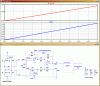
We got output from AD623 in the range of 0.5 to 1 v. But we can't get (4-20 ma) output from AD694. We made a connection as per the following circuit diagram. But we give 24 v supply and 10 micro farad. We get maximum output of 0.04 ma.we didn't add load resistor. Is this necessary to connect the load resistor b/w 11 & 5? What is your suggestion to get (4-20 ma)?
hi 457,
It is required that you follow the design instructions from the d/s when using a single supply and 0v to2V input range, ref this image.
Connect an Ammeter from pin #11 and 0V, this should show a 4mA thru 20mA for a 0v to 2v test input voltage,
Adjust Ra variable resistor to get the required span.
E
This site uses cookies to help personalise content, tailor your experience and to keep you logged in if you register.
By continuing to use this site, you are consenting to our use of cookies.


")

