Continue to Site

Welcome to our site!

Electro Tech is an online community (with over 170,000 members) who enjoy talking about and building electronic circuits, projects and gadgets. To participate you need to register. Registration is free. Click here to register now.

  • Welcome to our site! Electro Tech is an online community (with over 170,000 members) who enjoy talking about and building electronic circuits, projects and gadgets. To participate you need to register. Registration is free. Click here to register now.

Need advice on up/down counter - wheel controlled

Status
Not open for further replies.

jholder82

New Member
Hello all! I am new to electronics and set this as my first project, I am determined to see it to the end.

I am trying to make a LED 2 digit counter that is round, and has a wheel on the outside that spins clockwise to manually count up, and counter clockwise to manually count down.

Here is roughly what the device will look like.

http://i600.photobucket.com/albums/tt89/jholder82/diagram.gif

And here is the trigger I decided to use to make the wheel work

http://i600.photobucket.com/albums/tt89/jholder82/Wheel.png

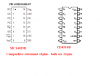
I modified this up/down counter schematic..

http://members.shaw.ca/roma/up-down.gif

to this...but I don't think it is going to work

http://i600.photobucket.com/albums/tt89/jholder82/up-down2.gif

Could you help me modify this schematic so it will work?
 
We can't modify anything we don't even know what IC's those are, nothing is listed in the schematic.
 
Make the count contacts conductive on one side and insulate them on the other with some glue or tape. One problem you might get with this approach is wear of the insulator and eventually exposing the conductor, making it work not as intended.

simple as making the "common" in your image go to voltage, and the counts to their respective pins on the ICs.

just a quick recommend, if you feel bold enough try searching for multiplexed displays, you can get a lot of displays with less components, but requires a little more "technique" to use.

Good luck and have fun with your project!
 
Any alternative for the wheel is a simple quadrature encoder, that will let the wheel fully spin for counting.
 
Make the count contacts conductive on one side and insulate them on the other with some glue or tape. One problem you might get with this approach is wear of the insulator and eventually exposing the conductor, making it work not as intended.

simple as making the "common" in your image go to voltage, and the counts to their respective pins on the ICs.

just a quick recommend, if you feel bold enough try searching for multiplexed displays, you can get a lot of displays with less components, but requires a little more "technique" to use.

Good luck and have fun with your project!
there must be one element by knowing the sequence or contact1 or contact 2 that follows, to enable the mode of counting.(decided on whether whether C1 follow2 or c2 follows1). As the concerned data sheets give full details
perhaps the OP can now improve on it.
 
Thank you guys for the great responses!


This design was actually planned to us the 4510 counter, and 4511 drivers.

I'm sorry if, I didn't completely understand your responses..still learning. But using the 4510 and 4511, do you think my modification would work?

Kakin, when you say route the common to voltage, and the counts to their respective pins....could you explain that to me?

Any alternative for the wheel is a simple quadrature encoder, that will let the wheel fully spin for counting.

I researched this a bit, would this encoder tell the difference between it spinning counting CW or CCW? and be able to count up or down? And how cost effective/difficult would this be for a beginner to implement?
 
Last edited:
Thank you guys for the great responses!
This design was actually planned to us the 4510 counter, and 4511 drivers.
I'm sorry if, I didn't completely understand your responses..still learning. But using the 4510 and 4511, do you think my modification would work?
Kakin, when you say route the common to voltage, and the counts to their respective pins....could you explain that to me?
I researched this a bit, would this encoder tell the difference between it spinning counting CW or CCW? and be able to count up or down? And how cost effective/difficult would this be for a beginner to implement?
The schematic that you have uploaded indicated 16 pin device for counter. it is pin compatible as CD4029. Please notice that 4510B has only 14 pins.
However, you need to study the Data-sheets and then work out. i suspect the way you have wired an NPN transistor, that you may check and correct.
 
Alright, I will definately read up on the datasheets, but I got this schematic from another site. They listed it as a 4510. Even when I look up information on it, they all display it as 16 pins in the drawings. Even in Eagle designer. I know it is a 14 pin, but I figured it was only displayed as 16 pin on the schematics and datasheets to make things easier.

I will try to keep reading, but the schematic I modified is what I have came to after studying for a while already. It would be nice to know exactly what counter I was using lol.

Thank you for the advice about the transistor. I will work on figuring that out.
 
Last edited:
Alright, I will definately read up on the datasheets, but I got this schematic from another site. They listed it as a 4510. Even when I look up information on it, they all display it as 16 pins in the drawings. Even in Eagle designer. I know it is a 14 pin, but I figured it was only displayed as 16 pin on the schematics and datasheets to make things easier.

I will try to keep reading, but the schematic I modified is what I have came to after studying for a while already. It would be nice to know exactly what counter I was using lol.

Thank you for the advice about the transistor. I will work on figuring that out.
I have a moderation
please see the following figure. fortunately both are compatible.
 

Attachments

  • CD4029 vs CD4510.PNG
    CD4029 vs CD4510.PNG
    25.6 KB · Views: 3,406
I'm sorry, but what is that comparison showing exactly? IT seems the 4510B in that diagram is 16pin too?
yes jholder82 !
the device datasheet says so. I am attaching the 4510B datasheet for ready reference.
Now you have to say whether you need the Pre-loading? or you need a simple 2 digit decade counter ( up counter)?

Do you really need the type of interface switch as planned by the orignal site that you quoted, for his specific design?
 

Attachments

  • CD4510B.pdf
    188.1 KB · Views: 294
I actually need a counter that can count up or down manually. But it has to be able to reset to a certain number. When powered on, I want it to start at 10. Then when I hit a reset button..no matter what count its at..it needs to go back to 10.

It doesn't have to be exactly like the sites, but since I am new to this, I thought it would be easier working off an existing schematic.
then you may go ahead without the mod you made on the 2N2222 and test it up.
 
Status
Not open for further replies.

Latest threads

New Articles From Microcontroller Tips

Back
Top