Geez, I haven't seen a PUT for over 30 years.
Muki got the symbol correct, but his circuit won't work.
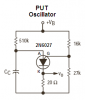
A PUT works as an oscillator by having the charging capacitor at its Anode, making a trigger voltage reference with a voltage divider at its Gate, and having the load to ground at its Kathode (spelling mistake because it is K).
When the capacitor's charging voltage at the Anode is a little higher than the gate voltage then the PUT conducts the capacitor's charge into the load.