Continue to Site

Welcome to our site!

Electro Tech is an online community (with over 170,000 members) who enjoy talking about and building electronic circuits, projects and gadgets. To participate you need to register. Registration is free. Click here to register now.

  • Welcome to our site! Electro Tech is an online community (with over 170,000 members) who enjoy talking about and building electronic circuits, projects and gadgets. To participate you need to register. Registration is free. Click here to register now.

Need a quiz buzzer

Status
Not open for further replies.
I think there are something wrong in your design:

- R10 should not be there.
- When pin#1 = 1, input is ignored.
- Why all input connect to GND?
 
Okay, Clifweb, I have had time to give further study to your sim schematic. There are still some mistakes, but we are getting closer. Compare my corrections in the attachment below with your copy and I think you will see what I mean.

Yes, milpitor, R10 must be in the circuit, else when V+ is applied there would be a direct short. Pin 1 is active lo until a positive going pulse is applied. R10 is a pull-down resistor that keeps it low, but also prevents a short circuit.

Oops: I just saw another error. The connection between the ground side of C3 and the ground side of the buzzer should be eliminated.

AllVol
 
Last edited:
doesn't the new wire from the bottom of C2 short it out?

also, the wires around /OE and LE look odd. not clear what's connect to what.
 
Last edited:
Thanks very much the buzzer is now working. The only problem now is that I have to reset it manually. I was now thinking if there could be an addition part that could be later on added that when the buzzer is pressed a countdown will happen that could be preset but that it could be change with easily. Maybe having a + or – to increase or decrease the time. When the countdown hits 0 a sound will be heard to give the signal that the time is up. This unit will be separate of this circuit but has to be able to connect to it.
 
Last edited:
This is the last simulation that I have run with I think everything is working but I have to reset each time. If there are some shot circuit please tell me. OE is connected to the ground. LE connected to pin 6 of the NAND gate.
 

Attachments

  • buzzer simulation.JPG
    buzzer simulation.JPG
    175.1 KB · Views: 391
Clif,

Put R10 back into the circuit as it is supposed to be. With it not in line, you are shorting to ground when you press the reset button.

AllVol
 
Hi, Phila,

Actually, according to the original schematic, his C2 should not even be there. But it's not really doing anything as it is.

AllVol
 
When I put R10 back the circuit is not working. As I remove it the entire circuit will work. Instead of the 22k I made it 1K and it work. Do you think that that is ok.
C2 is present on the original schematic.
 
Done on bread board

I have just built the buzzer on a breadboard to test it out before making it PCB. The circuit is working except that the 7 segment will only display the team number as long as that switch is pressed. Than it will be back to 0 after the switch is released. The buzzer is not working with the BC547 (As in the original schematic) the buzzer is not working at all but when instead of that I used the BC557 the buzzer kept on going the whole time. Can some one tell what he think is wrong.
 
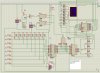
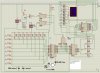
I only looked at it briefly but it seems to me that the idea is that the output of the LS30 will be low if no button is pressed and high if a button is pressed. this in turn is inverted by the LS00 which then is input to /LE on the LS373 and thus latching up the pressed button(s). so, I would follow those signals - pin 11 of the LS373 should be high when no buttons are pressed and then low when one has been pressed. If that's not the case, then trace the signal back. Based on your description, /LE is always high - I'd look at the LS30 and LS00 to see if they are properly connected.

Now, reset is a bit odd to me. pin 1 of the LS373 is output enable. pulled low, it enables output. pulled high, it puts the output pins in high impedence. I can only surmise that this is supposed to cause the LS30 to see high outputs from the LS373 and output a high which causes the state of the buttons to pass through the LS373. seems wrong to me. but presuming it can actually work that way, check that you have pins 1 and 11 of the LS373 properly wired - your schematic is unclear on that point.

Maybe a better solution for a reset is to use s1 to pull /LE high. this requires that no one is pushing any buttons. The LS373 will pass though the button signals (which are high), thus causing the LS30 to assert /LE high when s1 returns to the unpressed state. I'd use a resistor to ensure that you don't get a short circuit, though. debounce is a good idea but not really necessary, assuming that no one touches the buttons.
 
clifweb said:
I found this buzzer and I thought that I should try it with ISIS 6 Professional before building it on a PCB. When I press the button the number stays the same. What is wrong and how to fix it. Since even in the schematic the data is not all readable. If some one could provide me with a better schematic it would be great even if the number of team would have to be less but I prefer it to be able to have 8 players/teams. The schematic was taken from https://www.electronic-circuits-diagrams.com/funimages/funckt2.shtml


Try this simply one an anti coincidence circuit.
Sorry for my drawing.
Diode is 1N4156
Hope that it will help you!!!!!!
 

Attachments

  • ANTI COINCIDENCE CIRCUIT.jpg
    ANTI COINCIDENCE CIRCUIT.jpg
    80.7 KB · Views: 307
you sure about the lamps wired to the gate? the On Semi datasheet says gate current max is 50 mA.
 
Last edited:
philba said:
you sure about the lamps wired to the gate? the On Semi datasheet says gate current max is 50 mA.

Yeah. You can try this with only 3 PUT, 3 push button, 1 diode, 3 lamps, 2 resistor and a 12vdc power supply and see for yourself how its works. enjoy your games
 
If I were doing a quiz circuit, I certainly wouldn't do it that way - I'd use a uC. But I'm not. care to explain how it works?
 
That circuit won't work at all!
My guess is you've got the terminaly wrong on the diagram.
 
Hero999 said:
That circuit won't work at all!
My guess is you've got the terminaly wrong on the diagram.

Its really works. I do this circuit in vendo machine project. I replaced the lamp with homemade solenoid and win in the science fair.
 
Well I don't believe you!

Even though the schematic is worng you've probably built a totally different circuit.
 
I'm still waiting for an explanation of how it works. In particular, what are the bulbs' wattage? At 12V, it would have to be 600 mW to avoid exceeding the gate max current from the datasheet. Pretty dim... And a solenoid??? seems pretty far fetched. I would think you got the gate and drain mixed up but am willing to listen to what you have to say (other than "it really works").

Come on, Muki, tell us why it "really works".
 
Status
Not open for further replies.

Latest threads

New Articles From Microcontroller Tips

Back
Top