Continue to Site

Welcome to our site!

Electro Tech is an online community (with over 170,000 members) who enjoy talking about and building electronic circuits, projects and gadgets. To participate you need to register. Registration is free. Click here to register now.

  • Welcome to our site! Electro Tech is an online community (with over 170,000 members) who enjoy talking about and building electronic circuits, projects and gadgets. To participate you need to register. Registration is free. Click here to register now.

Need a quiz buzzer

Status
Not open for further replies.

clifweb

New Member
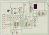
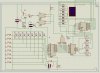
I found this buzzer and I thought that I should try it with ISIS 6 Professional before building it on a PCB. When I press the button the number stays the same. What is wrong and how to fix it. Since even in the schematic the data is not all readable. If some one could provide me with a better schematic it would be great even if the number of team would have to be less but I prefer it to be able to have 8 players/teams. The schematic was taken from https://www.electronic-circuits-diagrams.com/funimages/funckt2.shtml
 

Attachments

  • 1.gif
    1.gif
    25.1 KB · Views: 2,117
  • buzzer.zip
    19.9 KB · Views: 599
Looks like it should work? You have to reset it each time you want you ask the question, but that would be expected. And there is no timeout like I have on mine. Also, my buzzer goes back off after a couple seconds. But mine requires a PIC chip :) and I light up one of 6 LEDS.

My kids love the pic one I did. Not sure if I posted a picture, do not think I did.

But from a glance that looks OK. Looks like you reset the 373, a contestants button cause NAND to clock the flip-flop making sound and BCD shows who hit the button.

Did you build it on a breadboard?
 
I haven't tried it on a breadboard but as I sad i tried it on Proteus ISIS 6.7 Professional. and it didin't work. when i pressed the buttons the 7 segment stayed 0. my design is found in the buzzer.zip
 
Is ISIS6.7 Pro free? I can not seem to find it with google? Where is it and I will pull it and try it.
 
Yes, that circuit looks pretty good. can you look at various signals in ISIS. I'd check the inputs to 373, latch enable and output enable. look to see what's coming out of the '04.

by the way, you could implement a time-out by taking one of the button inputs and using a 555 timer set to what ever the timeout period is. I'd use 0.
 
Can some edit the schematic that I provided and give me the missing pins that are labelled on the schematic since not all pins are clearly read and I tried to connect those using data sheets but until now I haven't been able to make it work.
The top switch is being pressed and as seen in the image the display is still showing 0.
 

Attachments

  • buzzer simulation.JPG
    buzzer simulation.JPG
    186.6 KB · Views: 856
Perhaps there is a problem in your wiring. I notice you have your switches and pull-up resistors configured as in Figure 1 of my attachment. My thinking is they should be wired as in Figure 2. As you have them, there will always be a logic high present on the input of the 74LS373, which would give a "0" at the 7-segment LED.

Maybe you should try this rearrangement.

AllVol
 
Last edited:
that is how it ic connected. The switch has a wire going to the ic 74ls373 and from that wire there is another connection that first passes trough a resistor that to v+
 
They will both work but I agree that fig 2 is the more common approach. Note that fig 1 has a short circuit risk for any chip that can switch the pin between input and output. on a pic for example, enabling the port for output would toast the pin and maybe the chip. not the case here so it doesn't really matter. However, it is bad practice in general.

I wonder if the simulation sw has some sort of problem. still, you should approach this like debugging a real circuit. follow the signals - where they diverge from what they should be, you've found the problem. if you can't do that then you are definitely stuck in low gear as this is a pretty straight-forward circuit. I suggest you at least try as it will improve your electronics skill level a lot.
 
I can't solve this problem I have just started to study electronics. can you give me some tips on how to solve this at least.
 
do you understand what the various components do in your circuit? look at each one's datasheet. pay attention to the inputs and outputs. ISIS must have a way to look at the inputs and outputs of the chips. so, when you push a button, the 373's outputs will change. the top switch (input to d0) should cause the 373 to output a low on Q0. look to see if that happened. if not, there is your problem. if it's ok, look to the next chip, the 147. see if the outputs make sense given the inputs. if the low on input 1 causes the 4 outputs to be L, H, H, H (q0 - q3) then it's good. then follow the inverters ('04) and finally, check the 47.

by the way, original schematic used proper pull-ups.

another point, your isis diagram is kind of a mess, it's very hard to tell whether 2 lines are connected when they cross.
 
I am having a look to try to solve it. One way that it works is by removing the wire that is after the 8 resistors and connecting it to the ground. But the reset switch didn't work than and neither the buzzer. i had to turn the simulation on and off in order to try another switch.
 
Last edited:
PCB or circuit? I use eagle to create schematics and layout PCBs. I use switchercad/ltspice when I simulate - mostly analog or linear stuff. I never bother simulating digital as it's pretty straightforward. Generally, I just build the circuit and trace the signal when it doesn't work.

You should not be afraid to put a real circuit together. Use a solderless breadboard so you can make changes easily.
 
Probably not a really big thing, but the transistor (T1 on the original) you are showing in your schematic (as I write this, with no changes) is an NPN. It should be a PNP. Look closely for any other errors like this.

AllVol
 
Hope this simulation is easier to read. The 7 segment display works when a button is presses but the buzzer is not working and neither the reset switch. Please exam this so maybe I could get it to work.
 

Attachments

  • quiz simulation.JPG
    quiz simulation.JPG
    183.9 KB · Views: 416
Last edited:
Thanks, clifweb, for cleaning up the schematic. Much better.

My quick reading of the logic involved leads me to believe the buzzer only works if two buttons are pressed at the same time, but I have no clue why the reset is not working. However, on just a sim, I doubt there is any way you would know unless you check the logic level at pin 1 of the 74LS147 to see if it changed. Probably that would not tell you much unless you reran the sim, and then you have simply gone back to the ready state.

I think you are ready to make a hard copy, and see what happens.

AllVol
 
Status
Not open for further replies.

Latest threads

Back
Top