Hmmm ... seems like kind of a bizarre way to skin this particular cat, but if it works, hey, that's good.
I still don't get how the switches both enable the clock and stop the clock, but if you say it works, I'll take your word for it.
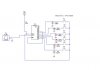
Of course, you also need a 10kHz source, but I suppose a 555 would do this nicely.