Ed Tessmacher
New Member
First, let me apologize by saying that I am just about as ignorant of electrical/electronics as a person can be. My basic skill level is, if you flip the switch and it comes on, great, but if not, call someone to fix it. ")
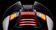
Having said that, here's the situation. I recently bought a new motorcycle. One of the "selling points" in the promotional material is that it had LED lighting, turn signals, brake lights, etc. When I took delivery, I was dismayed to find that the existing turn signals in the rear are not connected, although they do have the LEDs in the housing. There are those stalk "pumpkin" turn signals in the rear. So, hooking those up won't be a problem, because the wiring harness has a plug, but it goes to the pumpkins, not the in-body signals.
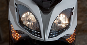
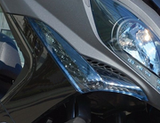
The front end is the problem. The housings are incorporated into the fairings, but the only working turn signals are in the mirrors of all places. Looking through the clear housing cover, one can see the holes in the housing where LEDs should be, but none are there, so it won't be a matter of just hooking up a plug.
I found a set of turn signals from an overseas parts dealer, but each one costs nearly $200 USD, not counting shipping. So, I had the bright idea (pardon the pun) to make my own.
I can obtain another set of these empty US turn signal housings for just under $35 USD. I have seen on eBay and Amazon, listings for 5mm, pre-wired LED bundles, costing around $8 for ten of them. That would be right at $100 bucks for two sets of turn signals. And if I screw them up, I haven't damaged the existing ones and can still ride.
These LEDs look like this (and I would use Amber ones) :

Since I know literally nothing about electronic specifications of this kind of thing, (and I apologize again, but I honestly consider it mumbo-jumbo designed to confuse people not in the business) I don't have the first clue how to go about doing this, other than simply epoxying LEDs into the holes in the housing, and hooking up all the red wires to a lead wire, all the black wires to another lead wire, and putting a plug fitting on the end of those lead wires to plug into the existing harness, or splicing those into the existing wiring for the turn signals.
According to the published information from one of the listings, the LEDs are:
Those numbers mean something, and since I do know that I'm working with a 12v DC system, I would think on the face of it that the information is important somehow.
I suppose what all of this information I've posted boils down to, is there anyone who can talk me through figuring out what to do about it (as if I were a 7 year old) without either blowing the entire electrical system in the bike, melting something, or doing some other irreparable harm?
Is this something that could even be done by an amateur working in the garage?
Thanks,
Ed
Having said that, here's the situation. I recently bought a new motorcycle. One of the "selling points" in the promotional material is that it had LED lighting, turn signals, brake lights, etc. When I took delivery, I was dismayed to find that the existing turn signals in the rear are not connected, although they do have the LEDs in the housing. There are those stalk "pumpkin" turn signals in the rear. So, hooking those up won't be a problem, because the wiring harness has a plug, but it goes to the pumpkins, not the in-body signals.
The front end is the problem. The housings are incorporated into the fairings, but the only working turn signals are in the mirrors of all places. Looking through the clear housing cover, one can see the holes in the housing where LEDs should be, but none are there, so it won't be a matter of just hooking up a plug.
I found a set of turn signals from an overseas parts dealer, but each one costs nearly $200 USD, not counting shipping. So, I had the bright idea (pardon the pun) to make my own.
I can obtain another set of these empty US turn signal housings for just under $35 USD. I have seen on eBay and Amazon, listings for 5mm, pre-wired LED bundles, costing around $8 for ten of them. That would be right at $100 bucks for two sets of turn signals. And if I screw them up, I haven't damaged the existing ones and can still ride.
These LEDs look like this (and I would use Amber ones) :
Since I know literally nothing about electronic specifications of this kind of thing, (and I apologize again, but I honestly consider it mumbo-jumbo designed to confuse people not in the business) I don't have the first clue how to go about doing this, other than simply epoxying LEDs into the holes in the housing, and hooking up all the red wires to a lead wire, all the black wires to another lead wire, and putting a plug fitting on the end of those lead wires to plug into the existing harness, or splicing those into the existing wiring for the turn signals.
According to the published information from one of the listings, the LEDs are:
- Super Bright 12v 5mm Orange / Amber Pre-Wired LED (Ships from US)
- 3-6v Working Range for maximum brightness
- Resistor built in to the pre-wired unit - Simply hook up power/ground for it to light
- Shrink wrapped connections with approximately 15cm (6 inches) of wire lead
- 20mA, 10,000-12,000 MCD, 600-610nm Wavelength, Clear Lens, 20-30 Degree Viewing Angle
- Super Bright 12v 5mm Orange / Amber Pre-Wired LED (Ships from US)
- Works well in automotive applications (12v charging system) 10-15v (not recommended 15v continuous)
- Resistor built in to the pre-wired unit - Simply hook up power/ground for it to light
- Shrink wrapped connections with approximately 15cm (6 inches) of wire lead
- 20mA, 10,000-12,000 MCD, 600-610nm Wavelength, Clear Lens, 20-30 Degree Viewing Angle
This single setup works well with the following voltages (you don't have to select a voltage when ordering): 10v, 11v, 12v, 13v, 14v and 15v. We recommend that you don't continuously run them at 15 volts, but they will take spikes as high as that without any issues at all. If you are looking for a lower voltage setup then take a look at our 9v or 6v setups that will cover the remainder of voltage ranges below 10v.
I suppose what all of this information I've posted boils down to, is there anyone who can talk me through figuring out what to do about it (as if I were a 7 year old) without either blowing the entire electrical system in the bike, melting something, or doing some other irreparable harm?
Is this something that could even be done by an amateur working in the garage?
Thanks,
Ed

") a motorcycle or car headlight might have been 55 watts or maybe 100 watts.
a motorcycle or car headlight might have been 55 watts or maybe 100 watts.

