Hi All,
1st off - audioguru -- LOL LOL LOL You're madder than a bucket of spiders - I like it
If you want to live in the UK to Know aout Big Brother watching you behind the wheel. Fixed speed cameras on almost every primary road, dynamically adaptable speed cameras on motorways. There's now talk of RF & GPS in new cars to monitor and log where and when you drive.
If you get from A to B in a certain time your nicked, it is going to be marketed as congestion charges with automatic billing - yeah right
2nd for mattpatt
My aplogies to mattpatt - I was a bit harsh - I have re-read the post and he (she) did say they where new to electronics, the manners thing i'll stick by!
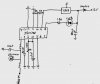
3rd - My Block Diagram
My thought process was running on black coffee at the time (the genuine filter stuff not instant) I think the Frequency multiplier might possibly have been a bit of a mistake
Charge Pumps are not the most reliable things in the world, And without some testing I'm not sure if it would be needed. But if it were, then eblc1388 has probably nailed the solution but, in my opinion, to get reproducable accuracy someform of divider/crystal based oscillator should be used again component tolerences would come into play
With hindsight I dont think an increase in frequency (over the ignition pulses) is called for.
4th for Ron h
In a caffeine induced stupper my thought process for the circuit operation was as follows
How to get a digital word (from the ignition) with which to compare a fixed preset (but alterable) value.
How can this word represent ever changing values (ignition pulses)
I originally thought about counting the pulses in a given time but then quickly realised it was not a time based value which was required but an actual numeric number based on the number of pulses received.
How could I stop the counter continously increasing the count to give a false positive condition. Thats where the bit on the right hand side of the diagrm comes in to play. By comparing the same D(n) pins from the counter but separated by a small time gap it would be possible to differentiate increasing and decreasing revs - so as to stop the counter counting up all the time If the revs were increasn the count would increase, if the revs decreased so would the counter and if the revs where constant so the count would not count (but hold its value) -'a closed loop'
This was to be done probably using a couple of LSB off the counter via a bit of logic (using a basic sample and hold idea)
If 4585 comparators were used they have the necessary logic to show >,= and < so if the 'greater than' pins used for the LED it would be continuously lit if the revs kept increasing as opposed to a quick pulse.
Incidently, I have just found a circuit based on four Op-Amps to sequentially switch four relays on an increasing input voltage - which I thought would be very suitable if mattpatt continued with the 2917 circuit he could have warning if potentiol DOOOOM before his engine explodes")
PM me if you want it published on the forum
Dotnet
1st off - audioguru -- LOL LOL LOL
You're madder than a bucket of spiders - I like it If you want to live in the UK to Know aout Big Brother watching you behind the wheel. Fixed speed cameras on almost every primary road, dynamically adaptable speed cameras on motorways. There's now talk of RF & GPS in new cars to monitor and log where and when you drive.
If you get from A to B in a certain time your nicked, it is going to be marketed as congestion charges with automatic billing - yeah right
2nd for mattpatt
My aplogies to mattpatt - I was a bit harsh - I have re-read the post and he (she) did say they where new to electronics, the manners thing i'll stick by!
3rd - My Block Diagram
My thought process was running on black coffee at the time (the genuine filter stuff not instant) I think the Frequency multiplier might possibly have been a bit of a mistake
Charge Pumps are not the most reliable things in the world, And without some testing I'm not sure if it would be needed. But if it were, then eblc1388 has probably nailed the solution but, in my opinion, to get reproducable accuracy someform of divider/crystal based oscillator should be used again component tolerences would come into play
With hindsight I dont think an increase in frequency (over the ignition pulses) is called for.
4th for Ron h
In a caffeine induced stupper my thought process for the circuit operation was as follows
How to get a digital word (from the ignition) with which to compare a fixed preset (but alterable) value.
How can this word represent ever changing values (ignition pulses)
I originally thought about counting the pulses in a given time but then quickly realised it was not a time based value which was required but an actual numeric number based on the number of pulses received.
How could I stop the counter continously increasing the count to give a false positive condition. Thats where the bit on the right hand side of the diagrm comes in to play. By comparing the same D(n) pins from the counter but separated by a small time gap it would be possible to differentiate increasing and decreasing revs - so as to stop the counter counting up all the time If the revs were increasn the count would increase, if the revs decreased so would the counter and if the revs where constant so the count would not count (but hold its value) -'a closed loop'
This was to be done probably using a couple of LSB off the counter via a bit of logic (using a basic sample and hold idea)
If 4585 comparators were used they have the necessary logic to show >,= and < so if the 'greater than' pins used for the LED it would be continuously lit if the revs kept increasing as opposed to a quick pulse.
Incidently, I have just found a circuit based on four Op-Amps to sequentially switch four relays on an increasing input voltage - which I thought would be very suitable if mattpatt continued with the 2917 circuit he could have warning if potentiol DOOOOM before his engine explodes
PM me if you want it published on the forum
Dotnet