Electro Tech is an online community (with over 170,000 members) who enjoy talking about and building electronic circuits, projects and gadgets. To participate you need to register. Registration is free. Click here to register now.
Welcome to our site! Electro Tech is an online community (with over 170,000 members) who enjoy talking about and building electronic circuits, projects and gadgets. To participate you need to register. Registration is free. Click here to register now.
Hello wizards!
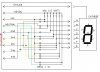
I am building gear position display for my bike. I hijacked this shematic from another site. Need confirmation from you, that is this working solution for that purpose?
You can also put two magnetic switches on the gear shift level, one to detect an up-shift and one to detect a down-shift which go to an up-down counter and display.
You have to initially synchronize the counter to the gear position, and also any time you happen to shift with the power off. **broken link removed** is a typical circuit for that and here is a kit you can purchase.
Good question.
My motorcycle gearshift won't move beyond 6 or below 1, so that would not be a problem for me.
If it is a problem, then you could use some gates to detect either a 1 or 6 from the 7-segment outputs, as needed to suppress the respective count up or count down clock.
The upper number is detected with one 8-input NAND gate to the "6" six active segments, and number 1 is detected with a 3-input NAND gate to the "1" two active segments plus an inverter connected to the middle segment (to ignore numbers 3 and 4).
This site uses cookies to help personalise content, tailor your experience and to keep you logged in if you register.
By continuing to use this site, you are consenting to our use of cookies.