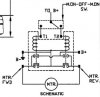
I had a contactor like this and with the way it is built, you can't change it's function, it has to have one or the other coil energized or nothing happens. At rest, both motor leads are at +12 volts and as you energize one of the coils, the lead on that side goes to ground. It's a very good relay for winches, but as it says, only for 5 minutes, on the one I had, the coil pulled 2 amps, 24 watts of heating, and there isn't enough surface area to dissipate the heat and mine did get so hot, I couldn't keep my finger on it!!
In your pictures on post #11, I see you have some definite purpose relays, and since the fan only draw ~7 amps, may I suggest you use 4 of them to power your fan, circuit drawing attached.
I showed the same two on delay timers as before, but there are other on delay timers out there, basically, the 91.5 timer you have will trigger the on delay timers which energize the 2 relays to send power to the fan, the diodes, as Mike stated are needed. Another timer is
https://www.electro-tech-online.com/custompdfs/2013/08/70200052.pdf , it can be ordered for 12vdc and is load independent. There others also, depending on locale and budget.
")