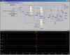
Ok, attached is a relay-only based design and simulation.
1. The timer is set up to free run with 1.5s On and 90s Off (backwards from what you were thinking). The timer function is simulated in the dashed box on the left.
2. It takes a total of three relays between the timer and the Cole-Hersee contactor. Relay U3 is a DPDT
12Vdc relay. It is used to invert the signal from the timer, gate the power to the motor, and serves as the "push-button" contact to trigger the relay toggle (
per the linked web page). Note the green trace V(B+). That shows when the motor will receive power (timer output inverted). Note that the current rating of U3 must be sufficient to switch the motor.
3. Relays U1 and U2 are
6Vdc DPDT relays that are effectively wired in series (per the linked web page). They form the toggle (flip flop).
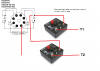
4. I didn't show all of the details inside the motor contactor in the dashed box on the right, but I did show the current to the two coils I(L1) and I(L2). Note that the two coils are alternately pulsed (during the 1.5s part of the timer cycle). Don't worry about the sliver; it is too narrow to effect the coils. The alternating nature of these pulses is what reverses the motor. Per the earlier suggestion, you will have to lengthen the 1.5s period to allow the motor to coast down before reversing it...