Continue to Site

Welcome to our site!

Electro Tech is an online community (with over 170,000 members) who enjoy talking about and building electronic circuits, projects and gadgets. To participate you need to register. Registration is free. Click here to register now.

  • Welcome to our site! Electro Tech is an online community (with over 170,000 members) who enjoy talking about and building electronic circuits, projects and gadgets. To participate you need to register. Registration is free. Click here to register now.

Motor Controller with multiple grounds, an issue ??

ramblin

New Member
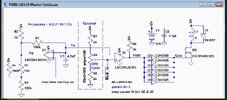
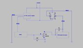
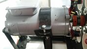
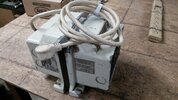
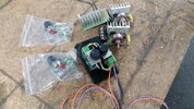
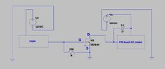
I just completed a motor controller with a circuit provided by our most helpful member "crutschow". Thank you ! It works really well with a 100 watt bulb as a load so far. I would like to drive a 90vdc PM motor @ up to 6-8 amps. Now I`m kinda new at this but I know the havic this motor can cause with back EMF, transients, est. I have all components on a single board, 12vdc PS, FWBR and PWM. My concern is how the grounds are connected. Do I have this right? I have a 10k res. and schottky in there but what stops it at the source ? All suggestions and criticism welcome. Please advise. Thanks
 

Attachments

  • Common grounds.JPG
    Common grounds.JPG
    54.3 KB · Views: 129
Last edited:
Just make sure you have good decoupling on both power supplies, close to their respective loads.

Use an electrolytic for bulk decoupling plus eg. a 0.1uF ceramic or polyester film in parallel with that.
 
I have a 0.1uf electrolytic coming off pos on the 12vdc power supply to ground. Thats probably not enough ? I have nothing on the FWBR. What would you suggest and where to put it ?
 
I'd put one pair of caps across the PWM power and ground, with the FET gate and source as short as practical, as the gate of a power FET has quite a high capacitance.

And one pair across the motor circuit, from near the FET source and motor positive.

The idea is they provide the bulk current pulses & take any energy recovered, so the power supply connections have a lot less noise and ripple.

(?? FWBR - No idea what you mean with that..)

You could also add another power diode across the FET source and drain, to protect it from negative-going spikes from the motor.
 
(?? FWBR - No idea what you mean with that..)


I`m probably calling it by the wrong name. Full Wave Rectifier Bridge. I`m new at this. I have it powered directly by my 120ac and the neg output of that bridge is what I share with the neg on the 12 vdc power supply for the PWM and that concerns me. What size caps do I need ? I have a 0.1uf on the pos 12volt PS now. That doesn't seem like enough for the high side. Do I need more for that ? Thanks !
 
I have it powered directly by my 120ac and the neg output of that bridge is what I share with the neg on the 12 vdc power supply for the PWM and that concerns me.

It definitely should concern you!
Doing it like that makes the whole circuit "live" at lethal voltages.

The negative is not a "ground" as it is, so the original title confused the question.

The 90V supply should come via a transformer so it is isolated from mains AC, and it's negative after rectification can be cross connected with the control circuit negative, and connected to true ground, for safety.

Or, next best, you need an opto-isolator & gate driver between the PWM side and the MOSFET / live side.
The PWM control side could then be grounded.
 
It definitely should concern you!
Doing it like that makes the whole circuit "live" at lethal voltages.
That is why I am here. I knew that could not be right. I have used optos before. Does that not just isolate the gate? For now I am stuck with the bridge. How do I isolate it ? An opto will not work for the source side. Is that correct ?
 
Please post your entire schematic. As it is, we're only guessing at what you really need to make the circuit work safely and reliably.

Each component needs to have a unique designator.
 
OK, like I said I copied the PWM from "crutschow" (thank you again). I changed the mosfet and schottky and added from there.
 

Attachments

  • crutschow circuit.JPG
    crutschow circuit.JPG
    98.1 KB · Views: 110
  • part2.JPG
    part2.JPG
    54 KB · Views: 104
Well that going to be difficult to answer with certainty. The motor been with me a long time and is missing the tag. It is an early Reliance (probably mid 70s), most likely a 90vdc @1hp rated @ 10 amps max, although this is uncertain. I have driven it for hrs. @ 100vdc @5-6 amps, 2500rpm with a varic and seen no heating at the commentator. I have driven it directly with the full wave bridge powered by 115 mains to 3200rpm @ about 9 amps under a load and still very little heating. I'm sorry this is the best I can offer. You may have a better idea what it is than me.
 

Attachments

  • motor.jpg
    motor.jpg
    2.3 MB · Views: 106
OK, so for safety you would need something like a 1500VA isolation transformer for motor power.

Or, isolate the gate drive circuit, which will need an auxiliary low voltage supply at the MOSFET side to provide the drive current.
 
Some comments about the Crutschow circuit :

1) The BCN014 has enormous gate C and miller C. 6000 pF. That leads to very high
gate charging currents to get it to switch fast, otherwise it will dissipate a
lot of power transitioning thru switching region.

2) The CD4050 does not seem to have a max rating on its Vcc buss current,
which I am very suspicious would cause logic failures trying to drive this kind
of load, the MOSFET gate C and Miller C.

3) There is no damping R between MOSFET gate and driver, to dampen L transients.
Thats a problem.

4) The diode is only rated for 1A, out of the question for use here.

5) I am in process of trying to sim this, have an issue with simulator, hope to
get resolved.

6) The MOSFET is only a 40V part, Vdsmax, so driving it in a system with 90V or more
......I must be missing something here.

Regards, Dana.
 
OK, Now we are getting somewhere. I actually have everything to do either one. 1st I have a 500va-120vac medical grade isolation transformer rated for 5 amps I would like to try. As long as I stayed under 5 amps that should work. Right ? This would be my 1st motor test to see if all this will even work. Where would the isolation transformer go in the circuit ? With an isolation transformer in there THAT could save everything. Is that correct ?
 

Attachments

  • isotrans.jpg
    isotrans.jpg
    4.4 MB · Views: 97
Some comments about the Crutschow circuit :

1) The BCN014 has enormous gate C and miller C. 6000 pF. That leads to very high
gate charging currents to get it to switch fast, otherwise it will dissipate a
lot of power transitioning thru switching region.

2) The CD4050 does not seem to have a max rating on its Vcc buss current,
which I am very suspicious would cause logic failures trying to drive this kind
of load, the MOSFET gate C and Miller C.

3) There is no damping R between MOSFET gate and driver, to dampen L transients.
Thats a problem.

4) The diode is only rated for 1A, out of the question for use here.

5) I am in process of trying to sim this, have an issue with simulator, hope to
get resolved.

6) The MOSFET is only a 40V part, Vdsmax, so driving it in a system with 90V or more
......I must be missing something here.

Regards, Dana.
Seems I got more problems than I thought.
#1 I'm using an IRF640 but that could be worse for all I know
#2 I ran the circuit as you see it with a 100 watt bulb as a load . I tried it with and with out the cd4050b and it made no difference to the bulb. It appeared on a scope about the same too, which was not to great.
#3 No, I have seen that recommended on other circuits. Didn't know what was necessary since as drawn its not high freq. nor probably needed in my application ?? Suggestions ??
#4 I also replaced that with a #12TQ158 150volt-15 amp, I'm sorry that may not have been on the 1st drawing I put up
#6 I'm sorry that may not have been on the 1st drawing I put up either ... Its a IRF640 200v-18a...I also have IRFB4615PBF-ND someone recommended that I haven't tried yet. Would that be any better ?
 
What is your motor supply V you want to switch ? What is your switching
freq ?

The bulb is essentially a resistive load, so generates very little inductive
transient V. Not a real good test. Motor different problem.

Gate R determination :


IRF640 much less C, so yes for this part probably better.


Regards, Dana.
 
What is your motor supply V you want to switch ? What is your switching
freq ?

The bulb is essentially a resistive load, so generates very little inductive
transient V. Not a real good test. Motor different problem.
I would like to use 115ac to the bridge and switch that. The crutschow circuit is duty cycle only which is exactly what I want. Now for freq. maybe you can tell me that. Crutschow says the frequency is determined by the value of R1 (100k) and C1 (4.7nf) using the formula ~1/(2.2*R1*C1). I don't know how to do that but my cheap little freq. counter say about 300hz. I know its slow because the bulb pulses more the lower you go. I figure it may be just fine for a motor controller. It would be nice to know what to change to go higher if need be. Do you like the idea of the isolation transformer in a few post earlier ?
 
The isolation transformer output would feed the bridge rectifier input, to give the 90V DC supply for the motor.

However, from the original schematic, it appeared you were using a smoothed 90V supply, which it turns out is not the case.

As you do not have any smoothing on the motor supply, it's not actually working as a true PWM controller, and may give some odd resonances as the PWM pulses drift through the AC half cycle timing.


You may be better off with a conventional "Drill speed controller" type circuit? Those interact with the motor back EMF so actually give pretty good control, rather better than an open-loop PWM system.

This is a typical circuit of that style - for a DC motor, add a bridge rectifier before the power input, but no smoothing! It relies on the zero crossing of the AC waveform for the thyristor to turn off at each half cycle.

speed-drill-controller-schematic.gif


And what looks to be a similar unit in ebay:

The use a suitable thyristor and an adjustable supply voltage to the gate (set by P1 in that circuit). Any time the motor back EMF drops below the gate voltage, the thyristor fires and maintains the motor speed.

Very simple, very reliable and that version even has a kind of "soft start" effect if you switch the input power to it, as C2 charges up to the set voltage over a second or two.

The TIC106D is rated 5A, you would need a higher rated one for a bigger motor, if you intended building one.
 
Seems I got more problems than I thought.
#1 I'm using an IRF640 but that could be worse for all I know
#2 I ran the circuit as you see it with a 100 watt bulb as a load . I tried it with and with out the cd4050b and it made no difference to the bulb. It appeared on a scope about the same too, which was not to great.
#3 No, I have seen that recommended on other circuits. Didn't know what was necessary since as drawn its not high freq. nor probably needed in my application ?? Suggestions ??
#4 I also replaced that with a #12TQ158 150volt-15 amp, I'm sorry that may not have been on the 1st drawing I put up
#6 I'm sorry that may not have been on the 1st drawing I put up either ... Its a IRF640 200v-18a...I also have IRFB4615PBF-ND someone recommended that I haven't tried yet. Would that be any better ?

Let me revise earlier post, the IRF640 or the IRFB4615 are too low a breakdown if you
apply line V to the bridge. Peak 110 Vac line V is ~ 160V and you should have a lot
of margin as ac line V's are pretty noisy. You should have TVS diode and or snubber
to protect MOSFET, and use a MOSFET with plenty of margin. I would gravitate to
250 - 300 V. If you stay with the PWM bridge approach.

The comments by rjenkinsgb excellent as well.


Regards, Dana.
 
You 2 guys have given me a wealth of information. I'm going to stick with the crutschow circuit for now and make it what it should be. I'm giving up on the isolation trans. idea and floating grd. and make it right ! If I can't make it work with what I learned in this thread I better quit right now. As for the thyristor type circuits I always thought that was a bad way to go. I started out with them. I have a junkyard of burned and repaired "light dimmers" I call them. They say 1000watt or 5000watt and they all got the same parts in there. They get hot as H... and have terrible control over all. I even put 2 together (it worked a little better) but eventually blew, always keeping the amps well below 4-5 which is where most of the testing is done anyway. Thanks for all the help. Really ! I'll fix it right and report back.
 

Attachments

  • scr.jpg
    scr.jpg
    4.6 MB · Views: 107

Latest threads

New Articles From Microcontroller Tips

Back
Top