Continue to Site

Welcome to our site!

Electro Tech is an online community (with over 170,000 members) who enjoy talking about and building electronic circuits, projects and gadgets. To participate you need to register. Registration is free. Click here to register now.

  • Welcome to our site! Electro Tech is an online community (with over 170,000 members) who enjoy talking about and building electronic circuits, projects and gadgets. To participate you need to register. Registration is free. Click here to register now.

Motor Controller with multiple grounds, an issue ??

ramblin

New Member
I just completed a motor controller with a circuit provided by our most helpful member "crutschow". Thank you ! It works really well with a 100 watt bulb as a load so far. I would like to drive a 90vdc PM motor @ up to 6-8 amps. Now I`m kinda new at this but I know the havic this motor can cause with back EMF, transients, est. I have all components on a single board, 12vdc PS, FWBR and PWM. My concern is how the grounds are connected. Do I have this right? I have a 10k res. and schottky in there but what stops it at the source ? All suggestions and criticism welcome. Please advise. Thanks
 

Attachments

  • Common grounds.JPG
    Common grounds.JPG
    54.3 KB · Views: 129
Last edited:
This is a rough sim to show, mainly, the issue with how much
current is being dumped into the gate driver buffer internal
supply rail which I think is a problem . Note its only 1 buffers
worth of drive, using the other 5 aggravates the problem.
Sim would not let me add the others due to licensing issues.

So in short a high current driver maybe makes more sense.
I could not find your diode anywhere on web.....

I estimated motor DC R for the example.

1688318823547.png


Regards, Dana.
 
There is a massive difference between a light dimmer and a speed controller; they are two very different animals, although online sellers may confuse the two and the circuits may look similar at a glance.

Light dimmers are direct phase control for resistive loads, speed controllers such as I gave the circuit for are back-EMF sensing for motor loads.
 
Quick question. I have some optocouplers on hand, all need a supply voltage around 5-15 volts. Where do you get this from without defeating the isolation purpose? Most IC regulators handle no more than 35-40 volts input. Can a simple voltage divider circuit using a 100k and 5k resistor work? That 5.6 vdc hooked to the dc side of the bridge. Am I gonna blow something up or create a hazard again?
 
You could input the 90V into a zener, say 60 - 70 V, to drop the V, and then
connect 3 term reg to that zener output.....Or use a power R to drop the V,
but then the input to 3 term reg become load dependent.

The above being active linear is power wasteful. The reg could be a simple
buck regulator, again with a Zener to get rid of excess V. Still not as efficient
as a total buck conversion but better.

Then there is this :


Use WEBENCH - https://www.ti.com/design-resources/design-tools-simulation/webench-power-designer.html


Regards, Dana.
 
Never thought it would be this hard to power an opto. Again nothing seems to fit the voltages I'm working with. These Buck LED drivers are already obsolete and others handle no more than 70volts input. I'm not finding my answer.
 
The simplest is to use something like this to power the "live" side:
 
Am I a rookie or what. I looked at transformers, voltage reg., est and never looked for board mt. converters. This is what I have powering the PWM. Thanks, Solved !
 
Never thought it would be this hard to power an opto. Again nothing seems to fit the voltages I'm working with. These Buck LED drivers are already obsolete and others handle no more than 70volts input. I'm not finding my answer.

I tried TI webench and it recommended several. One would assume they keep it up to date
but from experience always call. For any vendor linked earlier call their FAE and ask for
whats being recommended for new designs with your specs, thats the "safe" pay, but never
a guarantee, unfortunately.

Generally speaking a handful of customers drive the longevity of parts, when they abandon
a part all bets are off on continued production support.


Regards, Dana.
 
Would you guys once again have a look at the entirely revamped drive side of my circuit. The PWM side is completely isolated and outputs a very nice square wave from 1.5 - 12.8 vdc @ 3.9ma. The drive side is made with components I had on hand and may not be the best choice but all work together as setup. The output at the fet gate is about 3.8vdc. The output on my scope from the fet is a little fuzzy and jumpy but I have no resistors or caps anywhere except for the two 4.7Ks in the drawing. Why 4.7k? I have no idea but I seen them somewhere in the Gb of data I have meticulously studied thru in the last week learning all this. I have seen protection diodes, resistors and caps everywhere on every circuit I have viewed. Most circuits I find are using lower voltages. I have not yet learned where to put and how to calculate values for resistors, est. where they are needed. I HAVE NOT attempted to hook up the 120vdc yet. Also to note, I have gotten obsolete PCP116 optos to work well too but unable to make new 4N35s optos work at all. Also I`m using IRF740s mosfets but I cannot get the larger IRFP240s to work either. Could you please suggest any different components you think may work better and by all means suggest where and what to put for protection. And danadak, you were right about the CD4050. I could not make it work at all. Thanks guys !
 

Attachments

  • drive side.JPG
    drive side.JPG
    74.8 KB · Views: 98
You have a couple of problems I can see straight off:

The 5V supply should go directly to pin 8 of the VO2631; the 4K7 should be between VCC and V1 pins.

And, you have the MOSFET across the motor so it shorts the 120V supply, rather than in series with the motor!

Otherwise: You need either a logic-level MOSFET or use a 12V supply for the gate drive circuit (plus a small 5V reg, 7805, to drop that to 5V for the opto).
(The IRF740 is not guaranteed to start conducting until it gets 4V on the gate, and needs around 12V for lowest ON resistance).

You also need a low value series resistor between the 4421 outputs and MOSFET gate, to limit the peak current.
4.7 Ohms may be suitable.

I'd suggest adding some reservoir and decoupling caps to the power (across VCC & GND) for the opto and gate driver ICs, eg. 0.1uF ceramics on each plus eg. 100uF against the gate driver - that can deliver very high peak currents, so its power and the MOSFET connections need to be suitably rated and low impedance.

The gate-source resistor could be 10K, it's to prevent unintended conduction of the MOSFET when there is no gate drive for any reason.
 
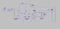
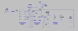
#1... "The 5V supply should go directly to pin 8 of the VO2631; the 4K7 should be between VCC and V1 pins".
OK, so 5vdc- no resistor to VCC on the opto. Didn't know how much power it could take, is why I did it. The gate driver wouldn't even work with the resistor. And 4.7K across A1 and VCC on the opto. Correct?
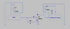
#2 .. "And, you have the MOSFET across the motor so it shorts the 120V supply, rather than in series with the motor!"
Yea, I see where I got that wrong. It was 1:45am and I put that in at the last min. Haven't even tried to hook that up yet. Thanks, I fix it!
#3 .. "Otherwise: You need either a logic-level MOSFET or use a 12V supply for the gate drive circuit (plus a small 5V reg, 7805, to drop that to 5V for the opto)". OK so instead of a 5v PS use a 12vdc and a LM7805 reg. (I got em) to power the opto, but 12v supply for the TC4421A. Is that correct ?
#4 .. "You also need a low value series resistor between the 4421 outputs and MOSFET gate, to limit the peak current. 4.7 Ohms may be suitable"
OK, From the "out" on the TC4421A to the mosfet gate a 4.7 ohm res. or a 4.7K ?
#5 .. "I'd suggest adding some reservoir and decoupling caps to the power (across VCC & GND) for the opto and gate driver ICs, eg. 0.1uF ceramics on each plus eg. 100uF against the gate driver"
OK, 0.1uF ceramics on the P.S. outputs. Got that. Where does the 100uf go ? I have seen a cap between G and S along with the res. and also seen a cap across G and D on the fet. What is correct ? Also I have seen big diodes on some schematics with higher voltages/current. Is this something I should look at ?

I will correct my drawing and repost it. Thanks !
 
Would you have a look at this and see if I cleaned it up ? Also is there anything else I need around the motor and 120vdc P.S? I have seen big diodes somewhere. How about anything across the drain and source ?
 

Attachments

  • driveside2.JPG
    driveside2.JPG
    99.7 KB · Views: 93
Didn't see this before but according to the 7805 data sheet little caps go on the reg. too ?
As long as the connections are all short, the caps already in the circuit should be adequate for stability on the 7805.

You have the 0.1uF on the driver IC connected to its output - that should also go between its supply and ground; other than that; it looks like it could work.

Just keep the connections between the driver IC and MOSFET source and gate short; if it's connected with link wires, twist those two together.

(Electrolytics are good for bulk power storage, but not at very high frequencies; the 0.1uF in parallel handles the fast edges of the current pulses, with the electrolytic cap providing some of the the sustained current during each pulse, to reduce load variations at the power supply and other components).
 

Latest threads

New Articles From Microcontroller Tips

Back
Top