Hello,
I've been trying this for a while (about some weeks).
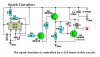
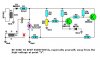
I built a mosfet driver to drive an ignition coil.
The first driver I've built was very simple, and the mosfet didn't turn off fast enough to generate the "kick effect/auto-inductance/back emf" (I don't know how do you call that ) so high voltage was not generated.
I could see that the MOST was not switching off, because I was using an 20A ammeter between the drain and the coil.
I tried with 2 mosfets, IRF3205 and IRF740.
Fail #1:
Sparks were not generated.
Mosfet didn't turn off.

Fail #2:
Some weak sparks were generated.
Mosfet didn't properly turn off.
(I could improve the performance by decreasing R2 value (10k) to 300R)

Fail #3:
Strong sparks were generated.
After a few seconds of working, the mosfet starts to conduct alone. So I have to turn off the supply to "reset" the circuit.

Any ideas?
I've been trying this for a while (about some weeks).
I built a mosfet driver to drive an ignition coil.
The first driver I've built was very simple, and the mosfet didn't turn off fast enough to generate the "kick effect/auto-inductance/back emf" (I don't know how do you call that
) so high voltage was not generated.I could see that the MOST was not switching off, because I was using an 20A ammeter between the drain and the coil.
I tried with 2 mosfets, IRF3205 and IRF740.
Fail #1:
Sparks were not generated.
Mosfet didn't turn off.
Fail #2:
Some weak sparks were generated.
Mosfet didn't properly turn off.
(I could improve the performance by decreasing R2 value (10k) to 300R)
Fail #3:
Strong sparks were generated.
After a few seconds of working, the mosfet starts to conduct alone. So I have to turn off the supply to "reset" the circuit.
Any ideas?