Electro Tech is an online community (with over 170,000 members) who enjoy talking about and building electronic circuits, projects and gadgets. To participate you need to register. Registration is free. Click here to register now.
Welcome to our site! Electro Tech is an online community (with over 170,000 members) who enjoy talking about and building electronic circuits, projects and gadgets. To participate you need to register. Registration is free. Click here to register now.
Hello;
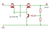
I post a schematic here My question is how to bias mosfet Vgs for such configuration . I need to shut the Line for anything in between 25 to 200 VDC . I know Vgs cant take more than 15V?
I am trying to avoid over voltage condition , by shutting off the supply in case it appears from the output or the right hand side of the schematic , anything entering from 24V to 200V is a threat and the MOS is required to put off the line untill the overvoltage condition is gone.
I didnt get you ? a 15V zener will not handel 200V DC in case its the over voltage condition . I try to turn on the transistor when there is enough current at 25V Dc to produce a Vbe of .6V .
I didnt get you ? a 15V zener will not handel 200V DC in case its the over voltage condition . I try to turn on the transistor when there is enough current at 25V Dc to produce a Vbe of .6V .
Is this that you want me to do? to bias the MOSFETS? . I want to know when the voltage is 200V will it not destroy the 15V zenner tied between Gate and source, till the BJT comes into action.
When the Vlolts are below 24 say 20V MOS are required to ne ON as automatically the BJT is OFF , but it doesnt seems to conducting?
ok...i think u should have a gate drive circuit to drive the gate of each mosfet. Gate drive can be opto-coupler and transistors joining together. Adding zener diode and resistor for overvoltage protection or adding clamping diode and resistor for faster switching turn on and off time.
ok...i think u should have a gate drive circuit to drive the gate of each mosfet. Gate drive can be opto-coupler and transistors joining together. Adding zener diode and resistor for overvoltage protection or adding clamping diode and resistor for faster switching turn on and off time.
Gate drive would require gate power and is only needed for high speed circuits. This is simple and there was no indication that it needed great response time, just an overvoltage switch.
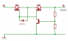
Ubergeek , thanks for the explanation . Actually I thought I have provided some less information actually I attach the schematic where My remote SMPS is getting Overvolted as shown. Please advise if to use N-MOS opr P-MOS ? . How the transistor BJT should be biased in such a situation and from where . The combination is confusing me if I use a crowbar is it feasable to protect the supply? . I add your basic circuit to the scheme please advise the turn on time if you can guess actually I havnt used MOSFET for such .
Apologies for the confusion actually I am confused too , Please have alook at the second attached image which I have added a little later above. It is to be noted that the Output is getting overvolted and not the input.
Not Me but its often happening as an accidental application at the remote sensor(25feet away) because of wiring mistake! when ever it happens. The sensor gets its supply from the mainboard. Now the Sensor is saved because of Crowbar but the supply blows off, any trick to save the supply.
Not Me but its often happening as an accidental application at the remote sensor(25feet away) because of wiring mistake! when ever it happens. The sensor gets its supply from the mainboard. Now the Sensor is saved because of Crowbar but the supply blows off, any trick to save the supply.
This site uses cookies to help personalise content, tailor your experience and to keep you logged in if you register.
By continuing to use this site, you are consenting to our use of cookies.