discostews
New Member
Hey,
I am looking for some help in the design of a circuit that i require for a project that i am working on at the moment.
The Basic idea is to implement a device that turns on when a strap is closed (conducting strap acting like a switch). When the strap closes, a PIC microcontroller will turn on, and the system will operate as normal. On the opening of the strap, the power to the PIC must remain on, but the PIC must know that the strap has been opened.
At this point, the PIC will use a radio transmitter to alert another system that the strap is open, wait for acknowledgement and then power itself off.
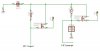
My current idea uses two MOSFET transistors to achieve this, and is shown in the diagram below. Closing the strap turns on one transistor (transistor 1) to power the PIC, which turns on another transistor (Transistor 2) to latch power through a seperate loop by turning an output port high.
An interrupt pin is used to sense the strap opening. Pull down resistors are used to keep the pins from floating. Power comes from the +ve of a battery and is to be attached to a "+5V" rail, that will power everything else.
However on building a test run of this circuit, i am gettin big voltage drops across the transistors which i cannot explain.
Is my circuit wrong? In my mind it seems great! Or do i need to redesign my whole method! I'm using MOSFETs, (ZVN3306A), and a 5V supply to test.
Any help or suggestions will be appreciated!
thanks for reading this far!!
DiscoStews
I am looking for some help in the design of a circuit that i require for a project that i am working on at the moment.
The Basic idea is to implement a device that turns on when a strap is closed (conducting strap acting like a switch). When the strap closes, a PIC microcontroller will turn on, and the system will operate as normal. On the opening of the strap, the power to the PIC must remain on, but the PIC must know that the strap has been opened.
At this point, the PIC will use a radio transmitter to alert another system that the strap is open, wait for acknowledgement and then power itself off.
My current idea uses two MOSFET transistors to achieve this, and is shown in the diagram below. Closing the strap turns on one transistor (transistor 1) to power the PIC, which turns on another transistor (Transistor 2) to latch power through a seperate loop by turning an output port high.
An interrupt pin is used to sense the strap opening. Pull down resistors are used to keep the pins from floating. Power comes from the +ve of a battery and is to be attached to a "+5V" rail, that will power everything else.
However on building a test run of this circuit, i am gettin big voltage drops across the transistors which i cannot explain.
Is my circuit wrong? In my mind it seems great! Or do i need to redesign my whole method! I'm using MOSFETs, (ZVN3306A), and a 5V supply to test.
Any help or suggestions will be appreciated!
thanks for reading this far!!
DiscoStews