Continue to Site

Welcome to our site!

Electro Tech is an online community (with over 170,000 members) who enjoy talking about and building electronic circuits, projects and gadgets. To participate you need to register. Registration is free. Click here to register now.

  • Welcome to our site! Electro Tech is an online community (with over 170,000 members) who enjoy talking about and building electronic circuits, projects and gadgets. To participate you need to register. Registration is free. Click here to register now.

MOSFET Headache

Status
Not open for further replies.
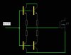
Some design used more than a resistor. An inductor also connected in series to get lower oscillation frequency near its switching frequency. This one applied when low power mosfet driving needed.

There also something interesting with fast rectifier. They used to reach high efficiency. Inductor and transformer without vibration, fast charge/discharge capacitor, and many more.
 
Normally a ferrite bead is just added in series with the gate - often its just put round the gate pin, there's nothing complicated about it!
 
More headaches! I will tell you that just before putting this thing together I tested it on the scope and it was hooked up negative to source, positive to load to drain. The pulse on the drain looked very much like the gate, only cleaner. But when I hooked it up, with no power to the gate, BOOM! :eek:

**broken link removed**

The MOSFETs are from "ON", part number: NTB125N02R, rated at 125Amps and 24volts EACH.

So as they were in parallel it would seem they would handle quite a bit. But when I hooked up the single 12volt battery( a small mobility vehicle type rated at 35ah ) which doesn't seem to be too much power, it failed. The gate had no power on it so the MOSFETs should not have conducted, right?

Any light shed on this catastrophe is greatly appreciated.

Thanks,
William
 
The gate is an insulator with a high capacitance. If your circuit doesn't have a resistor from gate to source to discharge the capacitance and turn off the Mosfets then they conduct enough to blow up.
 
Three, perhaps obvious, questions: 1) I could not find your circuit anywhere in this thread. Do you have some sort of drain resistor on the gates? You can get enough charge on a gate to turn on a mosfet, and if you don't ground it, it will stay on; 2) You say that you applied power to the source and drain, but nothing to the gate. How did you do that? Is your gate referenced to the same ground as the source? 3) Does each gate have its own resistor?

John
 
You say that you applied power to the source and drain, but nothing to the gate. How did you do that? Is your gate referenced to the same ground as the source?

I was hooking up the battery to the MOSFET switch, drain was hooked to the positive already, when I touched the source to the Neg terminal, BOOM.

3) Does each gate have its own resistor?

No.

BTW. I don't have a digital image of the circuit.
 
turbobill said:
I was hooking up the battery to the MOSFET switch, drain was hooked to the positive already, when I touched the source to the Neg terminal, BOOM.

Drain should have been hooked to low-side of load. Is that what you meant, or was the battery directly across the mosfet?

If drain was connected to load, then it sounds like your problem may be in the gate resistors and how you discharge the gates. BTW, one way to test a mosfet is to touch your diode meter to the gate and then check between drain and source. I was surprised how long an isolated mosfet will stay turned on. John
 
Here's how its hooked up.
 

Attachments

  • LifterCircuit.JPG
    LifterCircuit.JPG
    22.6 KB · Views: 219
What value is that inductor?

Blatman Bond said:
Driving such big N-MOSFET with 555 for high side.
The mosfet need at least 2Amp peak to reach nanosecond switching.
Which will never happen unless the inductance is low enough.
 
Also you need a low series resistor in series with the MOSFETs' gate to prevent high frequency oscillation - about 10:eek:hm: is normally sufficient.

What's the avalanche energy rating of the MOSFETs? It's possible that they're being zapped by the back EMF from the coil as you haven't connected a freewheel diode in reverse parallel with the coil.
 
Yes, 2 Amp peak for the driver. The gate current. 555 only provide mAs.
You need diodes. Otherwise drive it with synchronous driving.

Wow, its look like big big current. You should try it with small current first, if it success, you can try it for bigger and biggest. Or Just limit your supply current.
 
Last edited:
Would someone suggest a possible driver for these?

MOSFETs are from "ON", part number: NTB125N02R, rated at 125Amps and 24volts EACH.
 
Are you driving an inductor, transformer, or just solenoid. If that was inductor or transformer, you just applied a flyback design. Im using 2sk1342 900Vds mosfet operating at 300Volt for flyback. When it replaced with irfp460 500Vds it just fail and the mosfet broken.

You can use buffered cmos if there no driver available. For example, this driver has 80ns rise and fall time and only 1Amp peak. Just connect 4069 in paralel and buffer it with KSP2222A-KSP2907A BJT's. The resistor are 22 Ohms (gate resistor).
 

Attachments

  • buffer.JPG
    buffer.JPG
    19.5 KB · Views: 229
Found a couple of drivers that will work: Microchip MCP1406 and TC1413.

Am wondering if the circuit I'm switching is too SHORT. What I mean is, am I creating a short when the switch( MOSFETs ) are closed? The idea is to get pulsed DC from the coil. Have attached a pic that shows the basic layout, what do you think?
 

Attachments

  • RealDeal.JPG
    RealDeal.JPG
    973.3 KB · Views: 223
Is your inductor really just three turns of #4 wire wrapped around the 3" bobbin?

I would guess that's about 100 nanohenries, and the current from 12V would increase at the rate of about 120 amps/microsecond. Another way of saying, if you turn it on for more than a microsecond, bang!

Where's your fuse? (I mean other than the MOSFETs). Exploding batteries aren't pretty. Acid burns are forever.
 
It will be nice if you try it with big inductor, small power and slow switching (more safely). See what happen, or just simulate it with software. Then figure it out. Mosfets and mechanical switches are different.
 
It seems that your 555 work in low frequency, too low for your inductor.
An inductor will keep its current when shorted, charged when connected to voltage source, and instantly discharged when opened.
 
A 555 only works up to 500kHz.

To prevent excessive current you need to switch the MOSFET at 1MHz.

Use more turns on the coil to increase the inductance and calculate it (the formula can be found from Google). Remember di/dt = V/L so if you know how long the coil is switched on for and you know the voltage it's easy to work out the maximum current. You also need to be sure that the MOSFET is adequately avalnche rated for the energy stored in the inductor.
 
Status
Not open for further replies.

Latest threads

New Articles From Microcontroller Tips

Back
Top