logicnibble
New Member
Hi!
I'm building a circuit that is powered by mains and have a backup battery (12V sealed lead acid).
The battery powers the circuit when the mains is off (situation 1) and is charged when the mains is on (situation 2).
I would like to switch off the battery in case its voltage reaches its minimum to avoid battery deteoration.
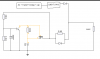
For that I have thought using a MOSFET as a switch in series with the battery.
But, as you might figure it out, in situation 1 there is current flowing FROM the battery and in situation 2 there is current flowing INTO the battery.
Does a single MOSFET (turned on) allow current in both direction, or do I have to use two MOSFETs for both situations? In that case how should be the driving circuit?
Thanks!
I'm building a circuit that is powered by mains and have a backup battery (12V sealed lead acid).
The battery powers the circuit when the mains is off (situation 1) and is charged when the mains is on (situation 2).
I would like to switch off the battery in case its voltage reaches its minimum to avoid battery deteoration.
For that I have thought using a MOSFET as a switch in series with the battery.
But, as you might figure it out, in situation 1 there is current flowing FROM the battery and in situation 2 there is current flowing INTO the battery.
Does a single MOSFET (turned on) allow current in both direction, or do I have to use two MOSFETs for both situations? In that case how should be the driving circuit?
Thanks!
")