Hi guys, hope youre doing well.
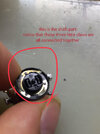
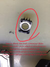
i have an old car stereo which ive been playing around to add a Bluetooth module to make some use out of it just for fun. The module has some pins used as physical play/pause vol+ and - buttons when connected to ground .i used the same component that has been used in car stereo board for volume control which is a rotary switch with 3 pins; i assumed these three are common , left and right pins, meaning when i rotate the switch right it connects the common pin to right pin and when i turn the knob left , the common and left pin are shorted. but playing around with multimeter buzz, i was shocked to see no matter in which direction i turn the knob all 3 left right and common pins get connected to each other. i though if there is anything happening its the PCB and board to blame so i tried to take out the switch and again noting changed, i took the actual switch apart and confirmed that ; yes its designed and built like that(please check the attached pics) i don't care what should i do about the module input im just really curious to know if any one knows if both vol+ and vol - have exact same behavior in this device how does the stereo recognize that I'm just now turning volume up or vise versa. or even why bother having two separate pin.
tnx for helping