Continue to Site

Welcome to our site!

Electro Tech is an online community (with over 170,000 members) who enjoy talking about and building electronic circuits, projects and gadgets. To participate you need to register. Registration is free. Click here to register now.

  • Welcome to our site! Electro Tech is an online community (with over 170,000 members) who enjoy talking about and building electronic circuits, projects and gadgets. To participate you need to register. Registration is free. Click here to register now.

MOS inverse switch not working

Status
Not open for further replies.

merzatt

New Member
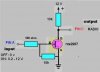
I am trying to create an inverse switch. The processor in my car turns on the extra 12v supply for radio for the purpose of backlight illumination when the parking lights are on. 12v passes through the illumination knob and the radio receives 0.2 - 12 v (at Pin A ) depending on the desired illumination level (usually 9-10 volts).

Radio head unit also has LCD screen that has night/day brightness setting. When the pin A has positive voltage, radio needs 0 voltage on Pin C to switch the LCD to night mode. But the current microprocessor doesn't provide this signal so I need an inverse circuit.

I jump wired the pin A to this circuit so I can use it as a signal. Pin A current is still supplying the backlight lamps of the radio as it is going to the circuit.
In summary,

Pin A -----------------> Pin C ---> Radio LCD
------------------ ------- -------------------------
0 volts ----------------> 12v -----> day mode (circuit does this correctly)
0.2 - 11.7v (variable)-> 0v -----> night mode

Problem with the circuit is, it does not drop the pin C (output) to 0 even though there is >5 volts on the MOS gate. What it does is this; from 0.5 to 11.5 volts, as the voltage on Pin A increases, voltage on pin C decreases the same amount. Shouldn't be the drain voltage 0 when gate has more than >5v? What am I doing wrong here?

I attached the circuit diagram and the MOS spec sheet. I am a newbie so please explain what you mean. Thanks!
 

Attachments

  • MOS circuit 1d.JPG
    MOS circuit 1d.JPG
    14.1 KB · Views: 251
  • nte2987.pdf
    27 KB · Views: 314
Last edited:
Shouldn't be the drain voltage 0 when gate has more than >5v? What am I doing wrong here?
Yes, it should according to the datasheet. The FET, being rated for 14amps, is awfully large for this small signal circuit I would think. It is possible that the FET has been damaged by ESD or too high a voltage on the gate. The max gate voltage for this device is 15V which is awfully close to what you'd get with the engine running. If you have another one, put a 13V zener from it's gate to source which will limit the voltage to a safe level and try again.
 
You probably don't even really need a FET for this. A 2N2222 transistor and some resistors might be all you need. Here is what we need to find out first:
What is the voltage on pin C of the radio with nothing else connected to that pin? ( I would guess 12V)
How much current is sourced by pin C when pin C is brought to ground? (It may be very little and in the 1-10ma range)
Once you have this info, I can tell you what circuit you need.
 
You probably don't even really need a FET for this. A 2N2222 transistor and some resistors might be all you need.

I used transistors NTE101, NTE103 before MOS and it did the same thing.

What is the voltage on pin C of the radio with nothing else connected to that pin? ( I would guess 12V)

Correct! it has 11.6 volts, as long as the ignition switch is ON. This does not change with radio backlights ON/OFF.

How much current is sourced by pin C when pin C is brought to ground? (It may be very little and in the 1-10ma range)

0.3 mA.

I made a discovery during measurement: while the multimeter leads connected to PinC and ground, I switched the multimeter from voltmeter to ohmmeter or ammeter. And guess what, the LCD went to DARK mode!:eek: I switched back to voltmeter or disconnect the lead from the multimeter, it goes back to DAY mode. Regardless of whether the radio backlights ON or OFF! I hope this will give you a clue! :D
 
Last edited:
I used transistors NTE101, NTE103 before MOS and it did the same thing.
I think I've figured it out. The dimmer is using PWM which means it is not DC, but rather pulsating DC at a rate that your eye can't see. Varying the duty cycle varies lamp intensity.
0.3 mA.
I made a discovery during measurement: while the multimeter leads connected to PinC and ground, I switched the multimeter from voltmeter to ohmmeter or ammeter. And guess what, the LCD went to DARK mode!:eek: I switched back to voltmeter or disconnect the lead from the multimeter, it goes back to DAY mode. Regardless of whether the radio backlights ON or OFF! I hope this will give you a clue! :D
Sounds like a 2N2222 with a 10K resistor on it's base will work. You can also use your FET circuit, but connect the input to the running lights circuit and not through the dimmer. That way you'll avoid the PWM of the dimmer.
If the dimmer wire is easier to get at, you'll need a diode and capacitor to smooth the PWM so the FET stays on between PWM pulses:
 

Attachments

  • MOS circuit 1d.JPG
    MOS circuit 1d.JPG
    17.4 KB · Views: 220
Last edited:
I think I've figured it out. The dimmer is using PWM which means it is not DC, but rather pulsating DC at a rate that your eye can't see. Varying the duty cycle varies lamp intensity.

Sounds like a 2N2222 with a 10K resistor on it's base will work. You can also use your FET circuit, but connect the input to the running lights circuit and not through the dimmer. That way you'll avoid the PWM of the dimmer.
If the dimmer wire is easier to get at, you'll need a diode and capacitor to smooth the PWM so the FET stays on between PWM pulses:

I may have burnt MOS. Can I use nte103 or nte101 instead of Mos?

Why do we still need 12v+ ? Pin C has 12v already. And all we need is to ground it right? I am just asking.
 

Attachments

  • nte103a.pdf
    49.4 KB · Views: 284
Last edited:
I may have burnt MOS. Can I use nte103 or nte101 instead of Mos?
Those are VERY old germanium transistors. Do you have anything else lying around?
Why do we still need 12v+ ? Pin C has 12v already. And all we need is to ground it right? I am just asking.
Correct. With a silicon transistor, you don't really need the 10K to 12V. With your nte101, I would leave it in because of leakage currents. A 2n2222 or 2n3904 or other small silicon NPN transistor is more suitable. You won't be able to plop a bipolar transistor into the FET circuit without mods. The circuit also depends on whether you still intend to use the wire off the dimmer or not.
 
Last edited:
Did I get the circuit right? I can go to shop tomorrow and buy the correct parts.

I have no choice but to use the wire off the dimmer.
 

Attachments

  • NPN circuit 1e.JPG
    NPN circuit 1e.JPG
    15.9 KB · Views: 207
You are close. The 500 ohm resistor limits the max charge current of the 47uF cap. The 10K first resistor limits the discharge rate into the base, so the transistor stays on between PWM pulses. The second 10K resistor ensures the transistor turns off when the input is off. Here is the corrected diagram:
 

Attachments

  • NPN circuit 1e.JPG
    NPN circuit 1e.JPG
    16.7 KB · Views: 252
Last edited:
Got it. Unfortunately Fry's don't carry 2n2222 (nte123) in stock. I have to wait until Monday to get it from another shop. Can I test the same circuit using nte85,101,103 or MOS (nte2987) until I get the parts?
 
You can permanently use the NTE85 in place of the 2N2222 with no changes. Almost any small signal NPN silicon transistor will work.
 
Ok. I have the 2n2222. I am building the circuit now. Pin A comes from car's central control module. Should I increase the 500ohm to 2.2k just to protect the microprocessor?
 
Last edited:
If pin A comes from the dimmer switch (is connected to the dash lights), 500 ohm should be fine as there is lots of current capability there. You don't want to make the resistance too high because the short PWM pulses must charge the 47uF up to supply enough voltage to turn on the 2n2222 via the 10K. 500ohms will only cause a max of 30ma to be drawn. You can use 470 or 560 ohm if 500 ohm isn't available.
 
Last edited:
Pin A comes from dimmer and I actually jump wired it therefore also connected to the backlight LEDs and microprocessor too. I wanted to start with the safest approach and used 2.2k. And it worked! Using 500ohm vs 2,2k effect the brightness of the LED by any chance?

Here is the diagram. Let me know using 2.2k is not a good idea. You are awesome. Thank you so much!
 

Attachments

  • NPN circuit 1e.JPG
    NPN circuit 1e.JPG
    16.4 KB · Views: 289
If the transistor doesn't turn on when the dimmer is turned all the way down, then you'll need to change the 2.2K to something less. ie: If the voltage on the 47uF cap is higher than 2V, when the dimmer is at it's minimum setting, then you are good to go with the 2.2K. The little bit of loading by the input to the circuit shouldn't effect the LED brightness at all.
 
If the transistor doesn't turn on when the dimmer is turned all the way down, then you'll need to change the 2.2K to something less. ie: If the voltage on the 47uF cap is higher than 2V, when the dimmer is at it's minimum setting, then you are good to go with the 2.2K. The little bit of loading by the input to the circuit shouldn't effect the LED brightness at all.

If I turn the dimmer all the way down, transistor doesn't turn on. But just a touch of dimmer increase is sufficient. Should I still lower the 2.2k?

Also do I really need the second 10k between the base and the ground (emitter)? I understand that this 10K resistor just discharges the capacitor more quickly right? But will it cause problems if the PWM duty cycle is reduced much?
 
Last edited:
If I turn the dimmer all the way down, transistor doesn't turn on. But just a touch of dimmer increase is sufficient. Should I still lower the 2.2k?
Only lower it to 500Ω if it bothers you. ;)
Most people don't dim their dash lights all the way down anyway.
Also do I really need the second 10k between the base and the ground (emitter)? I understand that this 10K resistor just discharges the capacitor more quickly right? But will it cause problems if the PWM duty cycle is reduced much?
Leave the 10K resistor in. It makes sure that the transistor will turn fully off when it is supposed to.
 
I would like to do this.
My dimmer on the new car radio works the opposite of the gauge lights.
so when dimmer is set to dim radio light is full brightness and vice versa.
Will this circuit work for me?

my wiring includes a separate illumination wire and dimmer wire.
the illumination wire works fine, turn on the headlight and it dims the radio lights.
the dimmer wire works the radio lights up and down but opposite of the gauge lights. So all I need is to "invert" the dimmer control.
SO i suppose when the dimmer voltage is zero the output is 12 and when the dimmer is 12 the output is zero.
 
Last edited:
The symbol in your schematic is wrong, it's a JugFET and you're using a MOSFET.
 
Status
Not open for further replies.

Latest threads

Back
Top