Mr RB
Well-Known Member
Carbonzit, no I didn't look at your LT Spice file in post #1, I don't use LT spice I use LT soldering iron, LT CRO and LT brain. ")
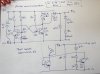
I put some parts values in the power mutivibrator, using the methodology and circuit I suggested all along the power multivibrator was tested first and some values chosen to give 9v and 44mA out with good efficiency. That is the "butter zone" I think for most 9v battery powered applications.
Then added the regulator that has worked so well in the past and did some voltage and current tests;
This was all done very rough and ready but proved the methodology; 1 that the power stage was first optimised for good efficiency near the max required current, then, 2 the regulator once added worked flawlessly to control that power stage and maintain output voltage.
This was all done very rough by plugging some parts values in, and measurements too were rough so allow a couple percent on all measurements. However I think it should be capable of 90% efficiency through a tuned Iout band, which is definitely in SMPS IC territory.
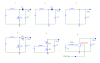
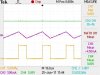
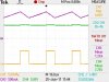
Note the waveforms (Q1 collector) are very clean and efficiently switching and the frequency deliberately chosen by the multivibrator values to give good power transfer from that 420uH inductor. It ran at about the same frequency with no inductor at all (just a resistor) showing the multivibrator doing it's job (as I earlier suggested it an be tuned independent of the inductor characteristics, allowing tuning for good efficiency).
I don't think this simple circuit would good be for higher power output levels but it worked pretty good at the Iout I chose (for use to replace 9v battery).
(edit) Checking the photos the resistors on the Q3 regulator base are 100 ohms and 4k7, (not 2k7).
I put some parts values in the power mutivibrator, using the methodology and circuit I suggested all along the power multivibrator was tested first and some values chosen to give 9v and 44mA out with good efficiency. That is the "butter zone" I think for most 9v battery powered applications.
Then added the regulator that has worked so well in the past and did some voltage and current tests;
Code:
[b]Power multivibrator first test.[/b]
Vout    Iout      Vin     Iin     Eff%   Freq    Duty
9.1v    44mA      2.99v   160mA   82%    26kHz   68%

[b]After adding regulator Q3[/b]
Vout    Iout      Vin     Iin     Eff%   Freq    Duty
8.85v   0mA       3.30v   5mA     0      Chaotic
8.85v   0.8mA     3.27v   10mA    24%    Chaotic
8.86v   3.3mA     3.25v   17mA    53%    83kHz
8.85v   8.8mA     3.22v   35mA    69%    45kHz
8.85v   19mA      3.05v   65mA    83%    31kHz
8.80v   27mA      3.08v   86mA    88%!   25kHz   67%
8.75v   40mA      2.97v   140mA   53%    25kHz
This was all done very rough and ready but proved the methodology; 1 that the power stage was first optimised for good efficiency near the max required current, then, 2 the regulator once added worked flawlessly to control that power stage and maintain output voltage.
This was all done very rough by plugging some parts values in, and measurements too were rough so allow a couple percent on all measurements. However I think it should be capable of 90% efficiency through a tuned Iout band, which is definitely in SMPS IC territory.
Note the waveforms (Q1 collector) are very clean and efficiently switching and the frequency deliberately chosen by the multivibrator values to give good power transfer from that 420uH inductor. It ran at about the same frequency with no inductor at all (just a resistor) showing the multivibrator doing it's job (as I earlier suggested it an be tuned independent of the inductor characteristics, allowing tuning for good efficiency).
I don't think this simple circuit would good be for higher power output levels but it worked pretty good at the Iout I chose (for use to replace 9v battery).
(edit) Checking the photos the resistors on the Q3 regulator base are 100 ohms and 4k7, (not 2k7).
Attachments
Last edited:
")