Hi, can anyone pse help a novice.
I am building a model railway control panel and I am stuck. On my layout I have station stops activated by the loco triggering a reed switch,
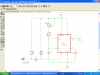
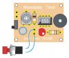
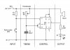
this works fine. I decided to add a monostable timer to automate the length of time the loco is stopped. A DPDT C/O MIN TOGGLE SWITCH controls this
ON manual stop - OFF no stopping - ON timed stop. I made a tester and all worked fine but I now have a problem that some of the timers
when switched on go straight into timed mode instead of waiting for the reed switch to trigger it. Can anyone suggest a retro fit to cure this ??
I ask for a retro fit because I have fitted 40 of these timers already and about 50% have this problem.
Thanks eddy

I am building a model railway control panel and I am stuck. On my layout I have station stops activated by the loco triggering a reed switch,
this works fine. I decided to add a monostable timer to automate the length of time the loco is stopped. A DPDT C/O MIN TOGGLE SWITCH controls this
ON manual stop - OFF no stopping - ON timed stop. I made a tester and all worked fine but I now have a problem that some of the timers
when switched on go straight into timed mode instead of waiting for the reed switch to trigger it. Can anyone suggest a retro fit to cure this ??
I ask for a retro fit because I have fitted 40 of these timers already and about 50% have this problem.
Thanks eddy
")