Continue to Site

Welcome to our site!

Electro Tech is an online community (with over 170,000 members) who enjoy talking about and building electronic circuits, projects and gadgets. To participate you need to register. Registration is free. Click here to register now.

  • Welcome to our site! Electro Tech is an online community (with over 170,000 members) who enjoy talking about and building electronic circuits, projects and gadgets. To participate you need to register. Registration is free. Click here to register now.

Model Railway LED Signals Circuit?

Status
Not open for further replies.

konakurt

New Member
Hello everyone! I am new to this forum, and I have a burning question to ask!

I have a model railway, and want to add a simple LED signals system, of a total of 16 green/red signals. I have everything I think I will need, but need help with a circuit diagram of how to put it all together (or better still, a SCHEMATIC diagram!).

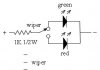
I have a 12v dc supply, 16 red and 16 green LEDs (all 3mm, 20mA forward diode current, where Vf typical = 1.9v for the Reds, and Vf typical = 2.1 for the greens).

I also have plenty of simple 3-pole (is pole the correct term for the terminal legs?!) 2-position ON-ON toggle switches.

Obviously for a railway, at any one time, I want EITHER a red OR a green switched on via the toggle switch, per signal.

With that all said, I am lost as I have never done this before! I can solder everything together, but need a clear schemetic DIAGRAM of the whole system.

If anyone could also calculate the exact values of any required resistors, that would be a great bonus :)

Kind thanks, Kona Kurt.
 
Last edited:
Here is a circuit for you. A 1K ohm 1/2W resistor is needed for each hook-up. If I understand the switch you are using it has 3 terminal on it. The center is the wiper and this is the one you connect the 1K resistor to. With the 1K resistor the LED current will be approximately 10mA and they should be visible.
The position of the switch will determine which LED is on in which position.
The + 12V supply is connected to the other end of the resistor. The - lead of the supply is connected to the two common leads of the LED's. The shorter lead is the - or the common lead for the LED's
 

Attachments

  • led circuit.jpg
    led circuit.jpg
    7.8 KB · Views: 805
Thanks K7elp60! Just a few more questions if that's ok. Am I right to read from your fiagram that for EACH signal, I can join the shorter - cathode leg of the green to the cathode leg of the red (ie, join the cathodes together)? I'm checking this because a diagram I found elsewhere suggests that to light up the LEDS, they must be joined + to - to + to - etc..? Also, at any one time, the 12v supply will be lighting up exactly 16 LEDs (regardless of whether they are green or red). Are you sure about the 1k resistors? And could I use '1/4W' ones instead?

Oh, and due to the slight difference in typical forward voltages between my red and greens, will the ciruit suffer at all if they are all switched to red, or all switched to green at any one time?

Thanks, KK.
 
Correction! That 'diagram' that I mentioned showing LED's legs connected -+-+-+-+ etc, was just a simple line of them in SERIES! Which I beleive is not relevent here..!?

KK, just confusing himself now!
 
Thanks K7elp60! Just a few more questions if that's ok. Am I right to read from your fiagram that for EACH signal, I can join the shorter - cathode leg of the green to the cathode leg of the red (ie, join the cathodes together)? I'm checking this because a diagram I found elsewhere suggests that to light up the LEDS, they must be joined + to - to + to - etc..? Also, at any one time, the 12v supply will be lighting up exactly 16 LEDs (regardless of whether they are green or red). Are you sure about the 1k resistors? And could I use '1/4W' ones instead?

Oh, and due to the slight difference in typical forward voltages between my red and greens, will the ciruit suffer at all if they are all switched to red, or all switched to green at any one time?

Thanks, KK.
You are correct a 1/4W resistor should be okey. R=(Vcc-VLED)/ILED. R=(12-2.0)/10mA. R=1K, P=EI, P=10X.01A, P=.1W. Normally double power rating for safety. Most red and green LED's have a about 1.8 to 2.0 volts drop @ about 10mA. The current between the red and green will vary a little with your circuit and the 1K resistor will be fine. I assumed that your railroad layout used the - from the power supply as the common. If the + is common then just reverse the LED leads and the power connections.
 
Status
Not open for further replies.

Latest threads

New Articles From Microcontroller Tips

Back
Top