Krumlink
New Member
After studying Transformers for hours, I found a simple circuit used for increasing power to a LED from a 1.2 to 1.5 Volt battery, because the LED you are using may require 2.0 to 3.0 Volts. This circuit uses parts that every hobbyist should have. If you dont have these parts, you may want to find a new career path 
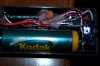
The circuit is extremely basic, using only 1 capacitor, 1 resistor, 1 LED, and 1 NPN 2222A transistor. It also requires 1.2V to 1.5V input (a AA battery or button cell). It is a very easy circuit, fun for anybody starting electronics. It is based off a inductor, or ferromagnetic core (in my case, a bolt). It MUST be magnetic, or it would do nothing except look like a coil of wire around a bolt. Mine happened to fit perfectly into a small AA battery holder, making it very compact and super sweet looking.
Parts required:
1x 0.1uf capacitor
1x 1k resistor
1x red LED
1x NPN PN2222A Transistor
1.2-1.5 Volt Battery
Some thin insulation wire (24 gauge with thin insulation wire, such as Cat5e wire)
A Bolt slightly shorter than a AA battery (if you want it to fit inside a AA battery holder)
Electricians tape
Tools Required
Soldering Iron
Wire cutter/stripper
Solder
Nippy cutters
Dremel (for cutting the hole in the case, my T13/4 LED fit perfectly snug in the case screw holder)
Pliers
STEP 1. Take the Transistor and Bend the Emitter and Collector 90 degrees to opposide sides (facing away from the Base). Take the LED and push the Leads together so they are close but not touching eachother. Then insert the Transistor between the leads (cathode to emitter and anode to collector) and push all the way through so it is almost laying on the transistor's labeled side. Solder and clip the LED leads.
STEP 2. Spread the capacitor's leads apart and put the resistor inbetween them so the resistor is in parallel with the capacitor. Make sure they are as close to eachother as possible. Clip the capacitor's leads and solder one side to the base. Make sure you have everything as compact as possible.
STEP 3. Take your bolt and some long wire and start wrapping it tightly around the bolt. Make sure it is uniform and neat, and it will look good. Have it end at the other side of the bolt (like a electromagnet nail). Take the other wire and wrap that round the wire and bolt too. End it on the opposide side you started. Solder 2 different sides together, and solder one of the remaining 2 sides to the capacitor resistor, and the other to the collector of the transistor.
**broken link removed**
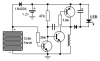
The above image is the circuit when finished. I substituted the 2700pf cap with a 0.1uf cap, but you can use anything within 0.1uf to 1000pf capacitor.
finish the circuit and you are done!
Mine works excellent and it looks awesome. Hope you have luck with yours.
If you want to have fun with your circuit, change around the capacitance of the cap on it. I am going to make a solar powered flasher next and post it in the projects forum
Here is the website just in case you want to look at it
http://www.cappels.org/dproj/ledpage/leddrv.htm#Rusty_Nail_Night_Light
NOTE: I will post pictures later today/tomorrow.
The circuit is extremely basic, using only 1 capacitor, 1 resistor, 1 LED, and 1 NPN 2222A transistor. It also requires 1.2V to 1.5V input (a AA battery or button cell). It is a very easy circuit, fun for anybody starting electronics. It is based off a inductor, or ferromagnetic core (in my case, a bolt). It MUST be magnetic, or it would do nothing except look like a coil of wire around a bolt. Mine happened to fit perfectly into a small AA battery holder, making it very compact and super sweet looking.
Parts required:
1x 0.1uf capacitor
1x 1k resistor
1x red LED
1x NPN PN2222A Transistor
1.2-1.5 Volt Battery
Some thin insulation wire (24 gauge with thin insulation wire, such as Cat5e wire)
A Bolt slightly shorter than a AA battery (if you want it to fit inside a AA battery holder)
Electricians tape
Tools Required
Soldering Iron
Wire cutter/stripper
Solder
Nippy cutters
Dremel (for cutting the hole in the case, my T13/4 LED fit perfectly snug in the case screw holder)
Pliers
STEP 1. Take the Transistor and Bend the Emitter and Collector 90 degrees to opposide sides (facing away from the Base). Take the LED and push the Leads together so they are close but not touching eachother. Then insert the Transistor between the leads (cathode to emitter and anode to collector) and push all the way through so it is almost laying on the transistor's labeled side. Solder and clip the LED leads.
STEP 2. Spread the capacitor's leads apart and put the resistor inbetween them so the resistor is in parallel with the capacitor. Make sure they are as close to eachother as possible. Clip the capacitor's leads and solder one side to the base. Make sure you have everything as compact as possible.
STEP 3. Take your bolt and some long wire and start wrapping it tightly around the bolt. Make sure it is uniform and neat, and it will look good. Have it end at the other side of the bolt (like a electromagnet nail). Take the other wire and wrap that round the wire and bolt too. End it on the opposide side you started. Solder 2 different sides together, and solder one of the remaining 2 sides to the capacitor resistor, and the other to the collector of the transistor.
**broken link removed**
The above image is the circuit when finished. I substituted the 2700pf cap with a 0.1uf cap, but you can use anything within 0.1uf to 1000pf capacitor.
finish the circuit and you are done!
Mine works excellent and it looks awesome. Hope you have luck with yours.
If you want to have fun with your circuit, change around the capacitance of the cap on it. I am going to make a solar powered flasher next and post it in the projects forum
Here is the website just in case you want to look at it
http://www.cappels.org/dproj/ledpage/leddrv.htm#Rusty_Nail_Night_Light
NOTE: I will post pictures later today/tomorrow.
Last edited: