Continue to Site

Welcome to our site!

Electro Tech is an online community (with over 170,000 members) who enjoy talking about and building electronic circuits, projects and gadgets. To participate you need to register. Registration is free. Click here to register now.

  • Welcome to our site! Electro Tech is an online community (with over 170,000 members) who enjoy talking about and building electronic circuits, projects and gadgets. To participate you need to register. Registration is free. Click here to register now.

Microchip Circuit - Getting Started

Status
Not open for further replies.

drkidd22

Member
Hello,

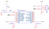
I'm putting together my own PCB with a PIC24FJ64GB004 (28-Pin SSOP package) and just started with the basic circuit following the datasheet. I'm posting it here to make sure I have it correct or if I'm missing anything so that you guys can advice. I will be using the PICkit 3 to program the device and I think I have the ICSP connector correctly wired.

Any ideas and input will be appreciated.
 

Attachments

  • basicPIC24Circuit.png
    basicPIC24Circuit.png
    19.4 KB · Views: 556
For starters, there are errors in the pin numbers and their associated functions in your schematic. For example, your schematic shows pin 20 as VUSB when the datasheet says pin 20 is Vcap/Vddcore. I didn't check all of the pins but there are likely additional errors.

Next, your DISVREG pin needs to either be connected to Vdd to disable the regulator or to Vss to enable the regulator. Depending on how you plan to power the core of the controller will dictate if you need to tie the Vcap/Vddcore pin to Vdd or connect a low ESR capacitor between it and GND. If you are running your board at 3.3V which is what your schematic says, you will need to ground DISVREG and use a 10uF cap on Vcap/Vddcore (See section 2.4 of the datasheet for more details).
 
Last edited:
So, I am working on a circuit in which the microchip will control the A3979 stepper controller. Since the microchip digital output is working at a Vdd of 3.3VDC and the A3979 is 5Vdc Vdd I want to know what will be the best way to isolate the switching of supply. Originally I wanted to use a BSS123 N-Chn MOSFET between the microchip and A3979, but I'm trying to consider opto-isolating the two devices. Any input on this?
 
The A3979 can be run on 3.3V just like the PIC24 you are using which means you can directly connect them together. If you can't do this on your board, the PIC24 has a number of 5V tolerant pins that could be used to directly drive the Allegro chip even if it's being run at 5V.

MOSFETs will not isolate your components if you truely need to do so. For that you will have to use optocouplers or some other form of galvanic isolation.
 
I can connect the pic to the A3979 directly as I'm just designing the board right now, so I can basically do whatever I want, just want to do it right once. The only reason I was thinking of isolating the A3979 from the pic is because the A3979 will have an input of about 24VDC for the motor and in case anything happened to it I want to protect the pic from the high voltage. I guess using the MOSFET will be useless then if I connect the pic to the A3979 directly saving me some space in the board or I could add the opto-isolators. Would I need current limit resistors between the pic and the A3979, maybe I should post up my circuit as I have it right now.
 
Only you can answer if isolation is necessary in your application. I've only needed it in a couple of special applications but I've never bothered on any of my hobby projects. Isolation is also a little more complicated than simply putting optocouplers between signal pins. You need to completely isolate the power and GND rails which complicates their design and leads to more material cost. Current limiting resistors between the PIC and the A3979 are not necessary when both are run at 3.3V.

Here is a board I worked on recently that is based around a PIC24FJ64GB004 (TQFP-44) and an Allegro A3995 (QFN-36). There is no isolation on the board because it would be more cost effective to replace the entire thing (1.25" x 1.5") than it would be to rework it.

**broken link removed**
 
Last edited:
Very nice, thanks for your information. My board size is right now at 1.5" x 2.8" with most 0805 components and I have mosfets in the circuit between pic and A3979, I also have OTG usb. Since this is only a hobby thing I will review my circuit and consider your suggestions. May I contact you over PM if I have any other questions? I want to do this just once and I'm almost done with the board design. I'm about to graduate and this is my first real own project.
 
I would prefer that you ask questions in this forum so other people can learn through your new experiences. A PM prevents that from happening and also limits you to answers just from me. As much as I pretend to be, I'm not the be-all end-all authority on electronics and there are plenty of other forum members who could have valuable insight!

Why don't you post up your latest schematic so we can see how you've progressed so far?
 
Last edited:
Thanks for your honest reply.
Here is what I have so far.
I've removed mosfets I had and still need to change a couple of things and also I need to assign the pins for connection between the A3979 and PIC24.
Like I mentioned initially I was going to use 5Vdc, but will limit to the 3.3Vdc and will prob remove the 5V supply and redo the 3.3.
One question I have is, is the step pin of the A3979 to be ran with PWN or can I just use set it low or high. I think PWM will be best and this will be more efficient and better to control.
 

Attachments

  • StepperControlPCB.pdf
    86.6 KB · Views: 290
The PWM pins on PICs are not intended for low speed applications like the step pin on an Allegro motor controller, however, they are flexible enough to be used in this manner. If you are concerned about having accurate step counts and using PWM, you will need to design your software in a way that keeps track of how many periods (steps) the CCP module has generated. PIC24Fs are capable of very fast interrupts (hundreds of thousands per second) so using a periodic timer interrupt to generate a step rate under 10K/sec would be easy to do. I've used this method with a dsPIC30F to control a 3-axis stage with stepper motors using 3 different timers without any issue. If you are only concerned about bulk motion or long periods of rotation, a PWM channel could be useful since once you set it, it will keep generating steps until you tell it to stop. The PIC you are using has a peripheral pin select feature which could allow you to seamlessly switch between these modes of operation.

A few quick things because I'm at work and don't have the time at the moment to thoroughly examine your schematic.

Vref on Allegro parts: Some (not all) Allegro parts have maximum Vref values that are significantly under the operating voltage of the device. Make sure this isn't the case with your part because you have it set to run up to 2V. Another thing I do is to use an external DAC (or build one using a PWM pin on the PIC) to generate the reference voltage to the motor controller. This will give you the ability to control maximum current to your motors in software which makes the board much more flexible.

Sense voltage: Most Allegro parts have a maximum sense voltage so make sure you don't violate it at your most extreme (highest current) operating conditions.

MS1 & MS2: Instead of controlling these with switches, consider using your PIC to control them. This gives you software control of how the microstepping functions which makes your board far more flexible.

USB: Check out the Microchip application notes on USB OTG. They have lots of examples and demonstration boards with schematics you can use to make sure your layout is correct.

UART: Consider adding a MAX232 IC to your board so you can break out a serial port. Since UARTs are trivial to configure, they can prove to be invaluable when trying to debug software if you don't have access to a true hardware debugger.

+5V: I don't see any components that require it other than USB which you have covered with the MCP1253. I would eliminate the current 3.3V power supply and change your switcher supply to output 3.3V.

Good luck!
 
Nice I will look into your suggestions.
MS1 & MS2: I had though about removing the switch for MS1 & MS2 and I will take care of that since it will be easier to control over software and will not need to access the device if installed in enclosure.
Vref: I'm good here, max Vref is 4V, I'm half way.
UART: I'll think about that and see what I can do.

Generating the reference voltage to the motor control with the pic PWM sounds like a really good idea, I will need to look into that.

3.3V: I've already completed the 3.3V switching supply.

Thanks for your help, this will really make the board smaller.
 
Ok, so I have built a protoboard based on the circuit I posted. The motor wants to turn when I run the program, but I thinking I have some timing problems. So the motor wants to turns, but it doesn't make a single turn at all. Below is the code I have been trying to get the motor to work with.

Another question I have is, see how I initialize the ports? If I declare ms1 before ms2 the pin state of ms2 doesn't change if I set to hi or low and check with scope, it's always output low. I've attached a copy of the data sheet from motor I'm trying to use.

Code:
#define FCY 8000000UL

#include <P24FJ64GB002.h>
#include <libpic30.h> 
 
_CONFIG1( FWDTEN_OFF  & ICS_PGx1 & GWRP_OFF & GCP_OFF & GWRP_OFF & JTAGEN_OFF) 
_CONFIG2( POSCMOD_NONE  &   I2C1SEL_PRI & IOL1WAY_ON & OSCIOFNC_ON & FCKSM_CSDCMD  & FNOSC_FRC & PLL96MHZ_OFF & IESO_OFF)
_CONFIG3(SOSCSEL_IO)
//Fast Internal RC (FRC) Oscillator 8MHz Clock Source

//Defines
#define                   sleep                    LATAbits.LATA0
#define                   ena                       LATAbits.LATA1
//#define                   pirsens                PORTAbits.RA2
#define                   rst                        LATAbits.LATA3
#define                   sr                          LATAbits.LATA4
//#define                   sense1                  PORTBbits.RB2
//#define                   sense2                  PORTBbits.RB3
#define                   step                      LATBbits.LATB4
#define                   ms1                      LATBbits.LATB8
#define                   ms2                      LATBbits.LATB7
//#define                   home                   PORTBbits.RB9
#define                   dir                        PORTBbits.RB15
 
main ()
{

    AD1PCFG = 0xFFFF;          //All pins are digital

    //Output Ports
    TRISAbits.TRISA0 =   0;      //Set sleep port as output
    TRISAbits.TRISA1 =   0;      //Set ena port as output
    TRISAbits.TRISA3 =   0;      //Set rst port as output
    TRISAbits.TRISA4 =   0;      //Set sr port as output
    TRISBbits.TRISB4 =   0;      //Set step port as output
    TRISBbits.TRISB7 =   0;      //Set ms1 port as output
    TRISBbits.TRISB8 =   0;      //Set ms2 port as output
    TRISBbits.TRISB15 = 0;      //Set dir port as output
 
    //Input Ports
    //TRISBbits.TRISB9 = 1;      //Set home port as input
    //TRISAbits.TRISA2 = 1;      //Set pirsens port as input
    //TRISBbits.TRISB2 = 1;      //Set sense1 port as input. Analog
    //TRISBbits.TRISB3 = 1;      //Set sense2 port as input. Analog

    //Output ports initial states
    sleep = 1; //Logic high is normal operation. When logic low minimize power consumption when the motor is not in use.
    ena = 1;    //Logic high, the outputs are disabled. Logic low enables all of the DMOS outputs.
    rst = 1;     //Logic high is normal operation. Pulse low resets the device.
    sr = 0;       //When the SR input is logic low, Active mode is enabled and synchronous rectification can occur. When the SR input is logic high, synchronous rectification is disabled
    step = 0;   //A low-to-high transition on the STEP input sequences the translator and advances the motor one increment.
    ms2 = 0;   //The input on terminals MS1 and MS2 selects the microstepping format.
    ms1 = 0;   //H H Sixteenth Step 4W1-2 Phase; L H Quarter Step W1-2 Phase; H L Half Step 1-2 Phase; L L Full Step 2 Phase
    dir = 1;     //The state of the DIR input determines the direction of rotation of the motor.
        while (1)
              {
__delay_ms(1);
ena = 0; 
__delay_ms(1);
LATBbits.LATB4 =   0;
__delay_ms(1);
LATBbits.LATB4 =   1; 
__delay_ms(1);
LATBbits.LATB4 =   0; 

             
              }
}

The below helped a little. The motor turns, but not smooth. I guess I gotta work on the timing diagram of A3979 shown in page 6 of the data sheet.
EDIT
Code:
while (1)
              {
__delay_ms(1);
ena = 0; 
__delay_ms(1);
LATBbits.LATB4 =   0;
__delay_ms(1);
LATBbits.LATB4 =   1; 
__delay_ms(1);
LATBbits.LATB4 =   0; 
__delay_ms(1);
ena = 1;
 
Last edited:
Thanks for your honest reply.
Here is what I have so far.
I've removed mosfets I had and still need to change a couple of things and also I need to assign the pins for connection between the A3979 and PIC24.
Like I mentioned initially I was going to use 5Vdc, but will limit to the 3.3Vdc and will prob remove the 5V supply and redo the 3.3.
One question I have is, is the step pin of the A3979 to be ran with PWN or can I just use set it low or high. I think PWM will be best and this will be more efficient and better to control.

Hi drkidd22. Personally, I would use a 1N4148 diode in series with a 10K resistor to MCLR, but I have heard that just resistors work too. I just use a diode with the resistor just to be on the safe side. Just another suggestion that you probably wouldn't need, but may be worth considering (depending on what you're using this for).

Good luck!
Der Strom
 
Thanks for your suggestion. So far it's working as it is. But I can't get the motor going. I'm using a 12V laptop power supply which can handle 3.3A output.
 
But I can't get the motor going. I'm using a 12V laptop power supply which can handle 3.3A output.

That may be your problem. 3.3A might not be enough to support the circuitry AND the motor. How big is the motor, anyway?
 
I've attached the data sheet from the motor. I have the current set for 500mA on the motor. Way below the power supply rating.
 

Attachments

  • N1728S87.pdf
    859.9 KB · Views: 383
I've attached the data sheet from the motor. I have the current set for 500mA on the motor. Way below the power supply rating.

Ok, but did you also take into consideration the stall current (for when the motor is first starting up) and the current drawn by the rest of the circuit?

You're right, it does seem 3.3A should be able to handle it, but it depends on the current drawn in the rest of the circuit. Is there any way you could hook the entire thing up to, say, a car battery? A car battery should be able to supply WAY more than enough current for it to work. Just something to experiment with, anyway :D
 
Status
Not open for further replies.

Latest threads

New Articles From Microcontroller Tips

Back
Top