Hi,
HELP PLEASE !
Daewoo no longer supply this transformer.............am trying to find a solution.
It is the L.V. transformer.
Info and photos, and service manual :
**broken link removed**
I have established :
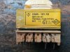
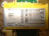
DMR-101FS, 5EPV041351, SEGI 98.J26 A
Terminal 1-2 230 VAC /50Hz
Terminal 4-5 13.0 VA C
Terminal 6-7 35.0 VA C
Terminal 8-10 3.0 VA C
but this is not clear to me................on terminal 4-5 ...........is 13.0 VAC the watts (volts x amps) or the voltage AC ?
I came across this webpage looking for a replacement transformer:
https://articulo.mercadolibre.com.a...rmador-para-placa-de-microonda-dmr-101-fs-_JM
but I am not prepared to pay 150 dollars for a second hand transformer, and it does not seem to correspond exactly anyway ??
Please refer to attached photos.
Many thanks for any help or ideas you may have to offer.
Kind Regards,
John
HELP PLEASE !
Daewoo no longer supply this transformer.............am trying to find a solution.
It is the L.V. transformer.
Info and photos, and service manual :
**broken link removed**
I have established :
DMR-101FS, 5EPV041351, SEGI 98.J26 A
Terminal 1-2 230 VAC /50Hz
Terminal 4-5 13.0 VA C
Terminal 6-7 35.0 VA C
Terminal 8-10 3.0 VA C
but this is not clear to me................on terminal 4-5 ...........is 13.0 VAC the watts (volts x amps) or the voltage AC ?
I came across this webpage looking for a replacement transformer:
https://articulo.mercadolibre.com.a...rmador-para-placa-de-microonda-dmr-101-fs-_JM
but I am not prepared to pay 150 dollars for a second hand transformer, and it does not seem to correspond exactly anyway ??
Please refer to attached photos.
Many thanks for any help or ideas you may have to offer.
Kind Regards,
John
")

