Continue to Site

Welcome to our site!

Electro Tech is an online community (with over 170,000 members) who enjoy talking about and building electronic circuits, projects and gadgets. To participate you need to register. Registration is free. Click here to register now.

  • Welcome to our site! Electro Tech is an online community (with over 170,000 members) who enjoy talking about and building electronic circuits, projects and gadgets. To participate you need to register. Registration is free. Click here to register now.

Transformer in Studio Monitor - How to test?

giddyup

New Member
Howdy!

I just joined, and I'm glad to be a part of an electronics repair for like this one.

I'm merely a student just getting started; so the ideas and questions are rambling in my head.

But for now; I'll stick to my issue at hand...

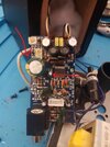
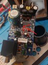
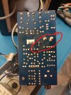
I have a Studio Monitor (M-Audio Audiophile AV 20) that I'm troubleshooting... I've already replaced 2 bloated and leaking bad CAPs in it.

The front light turns on, but I don't get any audio out of it. So, I wonder if there is something wrong with the transformer. (these monitors have no physical damage to them.)

I humbly ask for help in this troubleshooting journey... as I am just a student; and if I'm missing pertinent info here; or I'm not asking the right questions…
20230731_172552.jpg

Many thanks in advance.

Regards~
 
Verify that you have the 15 volt ac on the blue and blue wires. I you do then transformer is not at fault.

Also very helpful if you post photos of all boards and state which caps you have replaced. A schematic is also very useful
 
Ramondo, thank you very much for the insight.

I should have posted the board more clearly...
Here are pictures of the board. I've marked the replaced caps.
I'm also telling on myself with these solder joints... I tried to do this before I figured out how to take the board off of the plate; so it got a little hot... don't know if you recommend I do something to fix these joints (Or at least test that they're working or not somehow)

Unfortunately; I cannot find a schematic for this.
 

Attachments

  • Inked20230731_193318_LI.jpg
    Inked20230731_193318_LI.jpg
    3.9 MB · Views: 129
  • Inked20230731_193330_LI.jpg
    Inked20230731_193330_LI.jpg
    3.9 MB · Views: 124
  • Inked20230731_193338_LI.jpg
    Inked20230731_193338_LI.jpg
    4.4 MB · Views: 128
Thank you!

Another question... So I don't seem to be getting voltage to blue-blue. Which should be 15v 1.0a DC>
What if I used a bench power supply to bypass the transformer (bench power supply to the 2 prongs that the blue-blue goes to) and see if I can power it and get audio?

My only problem is I bought this: and it says 2AMP MAX... but the transformer puts 1A at 15.
Does this mean my unit will only draw the 1A required by the circuit... or will it flood it with 2A and ruin it?
If so, I will send it back and try to get a more expensive one that will limit the current.
1690848515365.png
 
Line transformers with AC input always have an AC output. A device will not push current through a circuit, the circuit will draw as much current as the resistance will allow. DO NOT shove dc where dc is not supposed to go. Do you have test equipment? Substituting a DC voltage IS acceptable if the circuit has been opened at the injection point and DC is expected there.. What is your relative understanding of electronic components? The datasheet below is the closest I could find.

Also the schematic sent earlier (AV30) does not match the chip shown in photo so be aware
 

Attachments

  • tda7491p.pdf
    1.4 MB · Views: 111
Last edited:
The first photo of the transformer shows what seems to be an inline fuseholder in the blue wire just above it?

Have to checked that fuse? It looks like the label says "T1" which would indicate a time delay (slow-blow) 1A fuse?
 
Line transformers with AC input always have an AC output. A device will not push current through a circuit, the circuit will draw as much current as the resistance will allow. DO NOT shove dc where dc is not supposed to go. Do you have test equipment? Substituting a DC voltage IS acceptable if the circuit has been opened at the injection point and DC is expected there.. What is your relative understanding of electronic components? The datasheet below is the closest I could find.

Also the schematic sent earlier (AV30) does not match the chip shown in photo so be aware
ramondo, I didn't receive a notification of your response; sorry for the delay.

I do have some test equipment. I have a couple multimeters, a 70Mhz Oscope, LCR-T4 Mega328 Digital Transistor Tester

My knowledge is limited at the moment; but I think I see what you mean; if the circuit is opened at a point where DC would normally be expected in the circuit, then you can "start" from that point in the circuit by applying your own appropriate DC current essentially isolating anything that is in the circuit BEFORE your injection point.(but making sure the circuit is open and only open going forwards, so you don't inject the DC backwards in the circuit??) Correct me if I'm wrong.

I missed the fact that the transformer says 15V 1A, but it doesn't say DC next to that, and the input to the transformer does say AC. so AC in AC out since the transformer is just taking an input and converting it to the output it needs for the circuit.; Right? (since it's not an "inverter" it's not converting to DC from AC or AC from DC)
 
The first photo of the transformer shows what seems to be an inline fuseholder in the blue wire just above it?

Have to checked that fuse? It looks like the label says "T1" which would indicate a time delay (slow-blow) 1A fuse?
rjenkinsgb

correct! There is a fuse in the plastic housing. That fuse is a 250V 1A fuse that has continuity and no signs of fatigue.
 
Now we guess. Assuming that your chip 7940 is close to 7941 in datasheet( you should trace pins to see if your chip matches component connections as shown on 7491 datasheet) then if no audio output left or right I would check power in to chip at pins 6-7,12-13 ,,,should be around 15 volts. then disconnect plug at J2 (vcc-gnd ) and provide 12 volts to positive leg of C23 with neg going to neg side of c23. You may have to provide some type of audio input at J1. You should also have some cheaper 8 ohm speakers connected to provide a load. I assume your board has a relay and you should check for the 3 volt supply to pin 1 of IC 2.
 
ramondo, just a quick update... I haven't been able to do the testing you mentioned above on the 7940...

But I did get a chance to test the transformer again… Because I originally was checking for DC at the blue-blue board connector.(I had this concept wrong)

Sure enough, when I test it as AC Voltage, I get 19.1V. So the transformer is ok (as long as that over-voltage isn't enough to be a problem, which I suspect it isn't.

Would the attached PDF maybe be the proper chip?
 

Attachments

  • TDA7490.pdf
    206.2 KB · Views: 103
NO. The chip on your board has 24 pins and is surface mount. Look at picture of chip you sent (7490) from top of datasheet, it is thru hole and a power chip. It may in the long run perform the same function but it would not fit on your board. The 7491 has the same profile and pin number as on your board.That is why I suggested following pins of chip to see if the components on your board match with components on datasheet page 29. EG. pins 20 and 21 go to relay and pins 6,7,12,and 13 go to vcc (16 volt dc). If they do then YOU can ASSUME the 7491 and 7490 are the same.

Do you have a small three pin device near the relay labeled IC2?
 

Latest threads

New Articles From Microcontroller Tips

Back
Top