Continue to Site

Welcome to our site!

Electro Tech is an online community (with over 170,000 members) who enjoy talking about and building electronic circuits, projects and gadgets. To participate you need to register. Registration is free. Click here to register now.

  • Welcome to our site! Electro Tech is an online community (with over 170,000 members) who enjoy talking about and building electronic circuits, projects and gadgets. To participate you need to register. Registration is free. Click here to register now.

mic preamp

Status
Not open for further replies.

dragon91

New Member
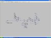
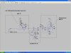
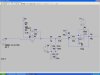
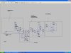
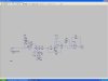
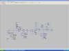
hello everyone... I have recently made a mic preamp( non-inverting with 2nd order buttersworth filter)... the problem with the circuit is that the output of my opamp is not stable... the signal is constantly varying from 0 and 3V. Can u tell me what the problem is......... here is my circuit diagram.........
 

Attachments

  • schematic..JPG
    schematic..JPG
    106.8 KB · Views: 263
better description

Here is a better description with the picture of what I am doing and using....
 

Attachments

  • schematic..JPG
    schematic..JPG
    124.8 KB · Views: 203
mic opamp bias

You bias the second opamp, but not the first one.

I cant bias the first one as it is built in within the microphone.... it is a mic integrated with an amplifier.. it comes in one package and there is no way I can provide a dc offset for it..... without taking apart the mems mic.....
 
Presumably you're only simulating this? - you can't just throw a few components together at random to try and replicate an amplified mike. The opamp isn't biased, and it won't work if it isn't.
 
The second opamp is an oscillator because its gain is 83, not 10.
 
gain same for both opamps

So the gain needs tp be the same for both amps at both stages???? I really dont understand why I need to dc bias the first stage when it alrady has a dc offsrt of 1.1V and I decoupled the output and input of the opamp.... can u please clarify this for me... can u show me how the circuit should be....
 
I didnt get the part when u said the 2nd opamp is an oscillator???' that is exactly what is happening at the output of my opamp... It constantly oscillates between 0 to 3V. why does that happen???? because of the dc offset or the different gains at each stage????
 
I have improved the gain.... but what should I dc bias...... should I dc bias the Vcc to the microphone????????
 

Attachments

  • current design 2&#46.JPG
    current design 2&#46.JPG
    124.4 KB · Views: 182
how can I bias the first opamp.... should I bias the vcc of the opamp... because thats the only thing I can bias without taking apart the mems mic with an integrated amplifier.......
 
how can I bias the first opamp.... should I bias the vcc of the opamp... because thats the only thing I can bias without taking apart the mems mic with an integrated amplifier.......

You keep saying this - if the first opamp is inside the mike, why are you showing it on the circuit? - because the diagram as shown won't work. If there is an opamp in the mike, then it is biased - it won't work otherwise.
 
The second-order Sallen and Key lowpass filter has a certain amount of max gain to be a Butterworth filter. If the gain is too high then it oscillates.
I make this type of filters using a gain of 1 for the opamp, same value resistors and the capacitor values are 2:1, or use the same value capacitors and a fgain of 1.6.

You can use the Texas Instruments Filter-Pro program to calculate lowpass filters with any amount of gain but the capacitors and resistors have odd values.
 
ok... so I can only get a gain of 1 from the buttersworth low pass filter..... so the capacitor values should be 2:1 meaning what are we comparing the ratio with??? like 2 being the capacitors and 1 is what?????
The second-order Sallen and Key lowpass filter has a certain amount of max gain to be a Butterworth filter. If the gain is too high then it oscillates.
I make this type of filters using a gain of 1 for the opamp, same value resistors and the capacitor values are 2:1, or use the same value capacitors and a fgain of 1.6.

You can use the Texas Instruments Filter-Pro program to calculate lowpass filters with any amount of gain but the capacitors and resistors have odd values.
 
DO U MEAN SOMETHING LIKE THIS... I have used a unity gain low pass butersowrth filter and another opamp to amplify the signal.....
 

Attachments

  • ANOTHER DESIGN..JPG
    ANOTHER DESIGN..JPG
    130.2 KB · Views: 163
I think this works... I forgot to ac couple the third stage.....
 

Attachments

  • another design2..JPG
    another design2..JPG
    103.5 KB · Views: 150
Status
Not open for further replies.

Latest threads

New Articles From Microcontroller Tips

Back
Top